Engineering Design Portfolio — Embedded Systems & Mechanical

ESP32 Mini RC Car

3D-Printed Chassis · ESP-NOW Wireless · Custom PCB · Feb–Mar 2026
XIAO ESP32-C3 TB6612FNG Dual H-Bridge Metal-Gear Micro Servo Steering ESP-NOW · No Router Assembled & Tested
Fusion 360 Chassis Creality K1C Custom PCB — KiCad
Result Designed and built a fully custom RC car from scratch — chassis in Fusion 360, electronics on breakout boards, wireless control via ESP-NOW. Fully assembled and driving; custom PCB in progress.

Started this because I couldn't find an RC car kit that didn't feel like a toy. Designed the chassis in Fusion 360, printed everything in PLA — including the wheels. ESP-NOW ended up being the right wireless choice once I fixed a channel mismatch that was causing complete dropouts. The current build runs on breakout boards and jumper wires; a custom PCB is in progress — started in EasyEDA, now migrated to KiCad — targeting JLCPCB manufacture in the coming weeks.

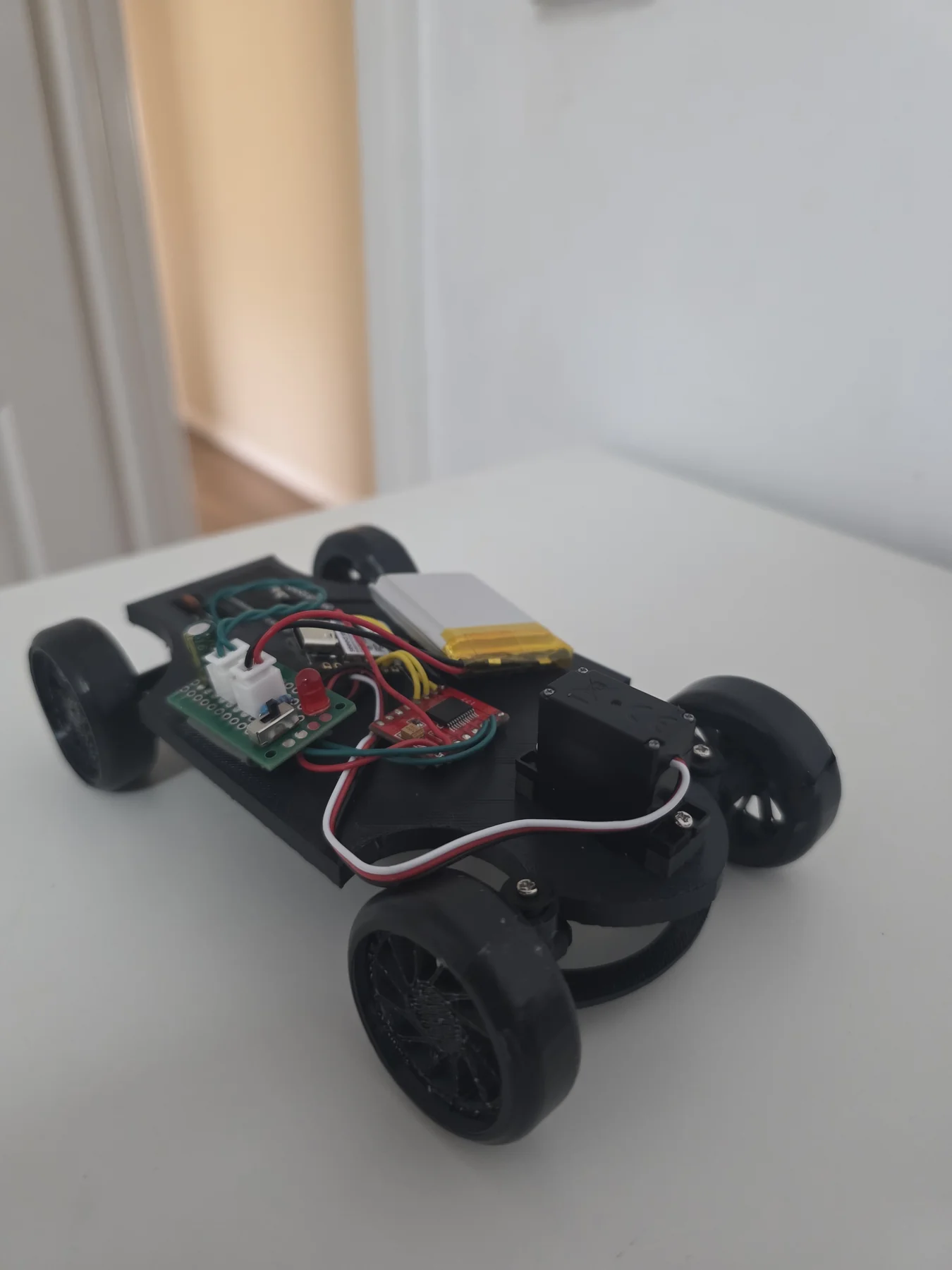
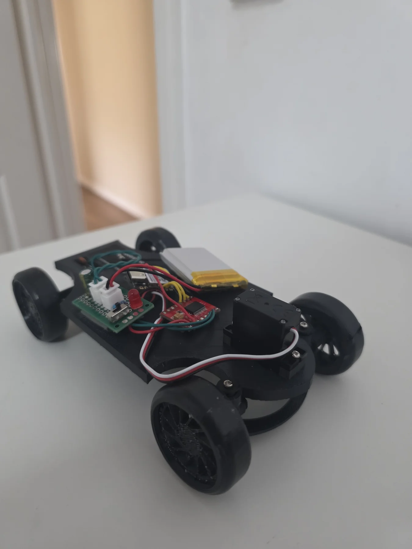
RC Mini Car side view
Side Profile — 3D Printed Chassis
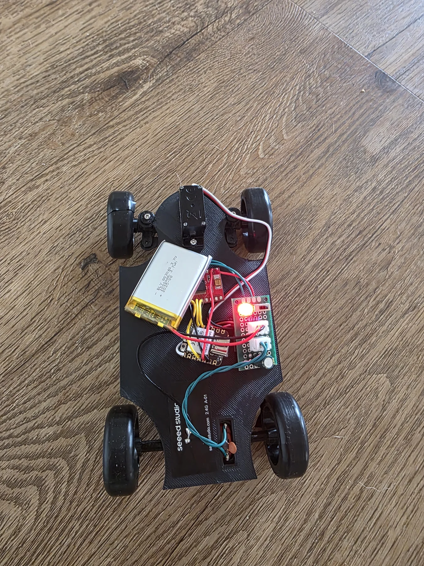
Top view
Side view
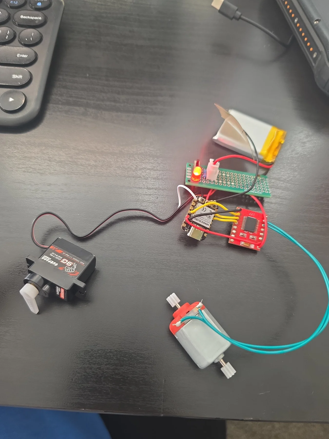
Assembly
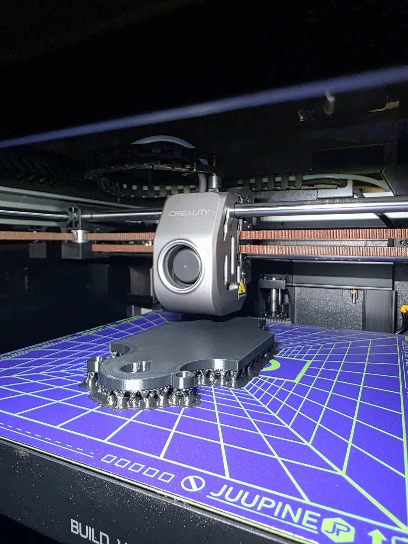
3D printing
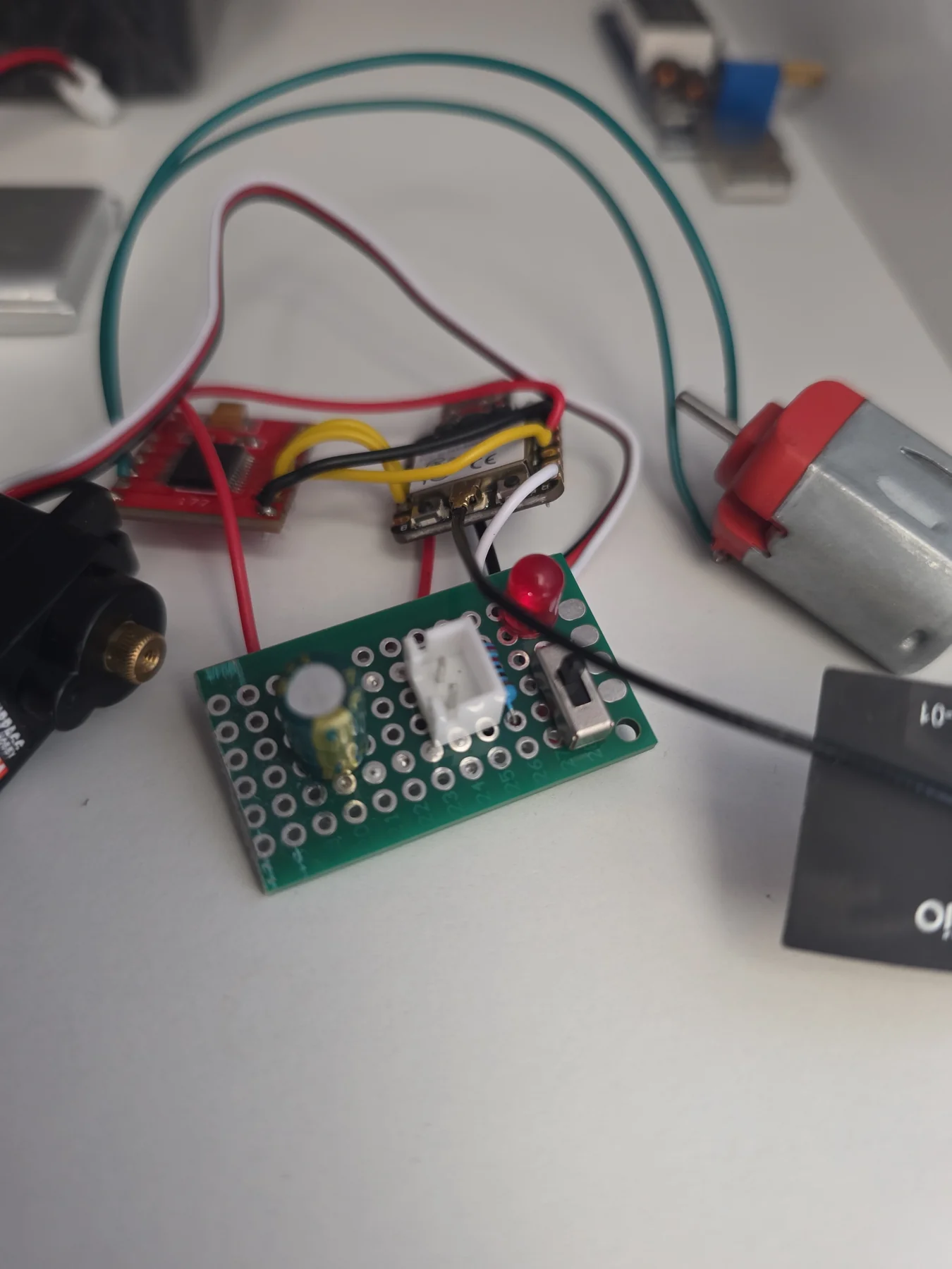
Circuit
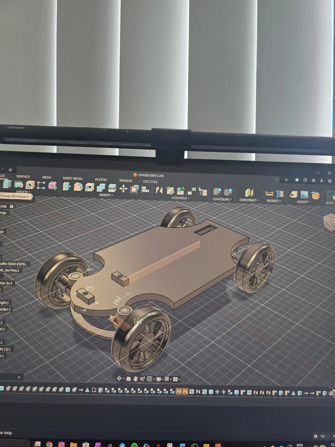
3D model CAD
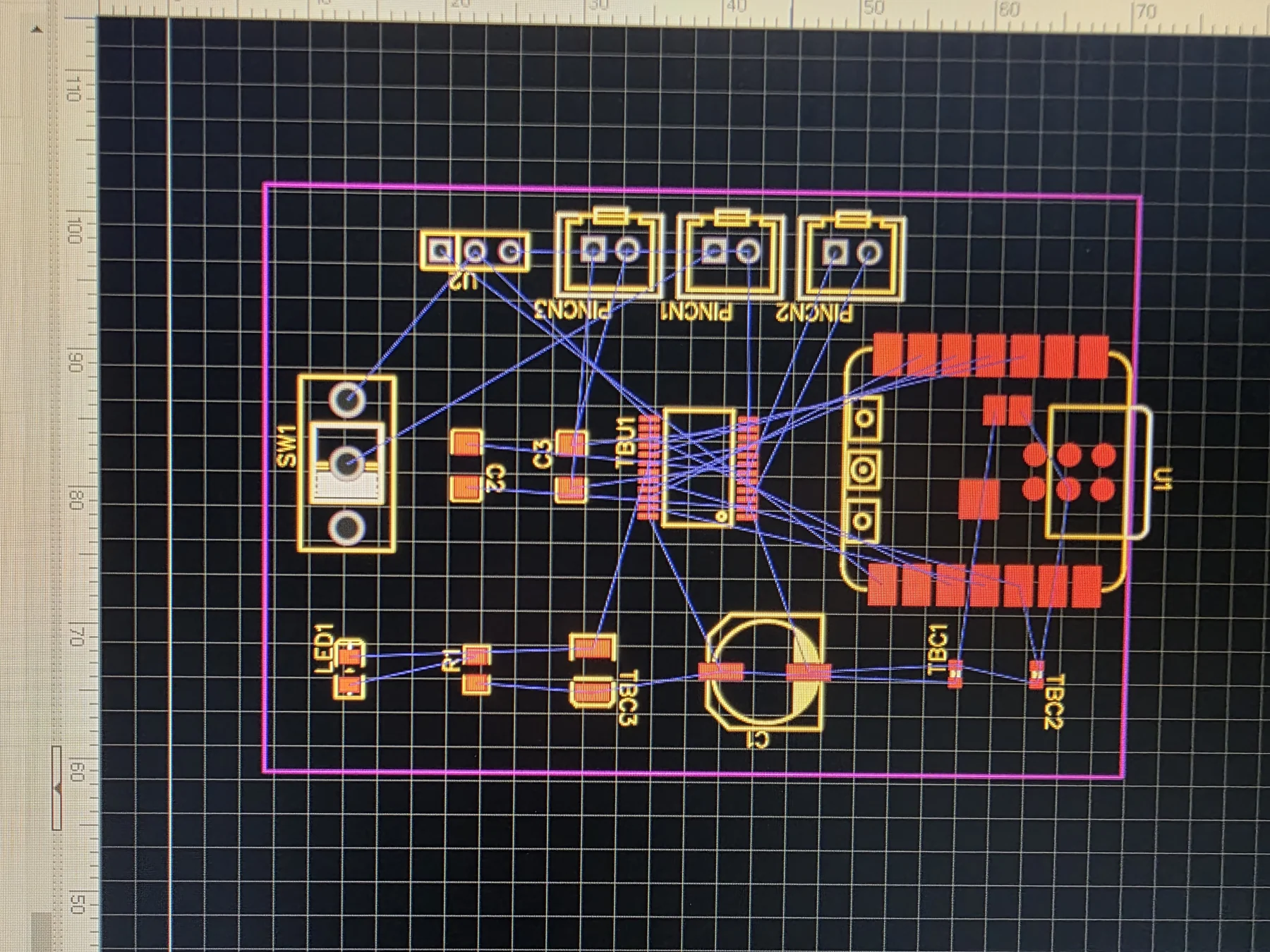
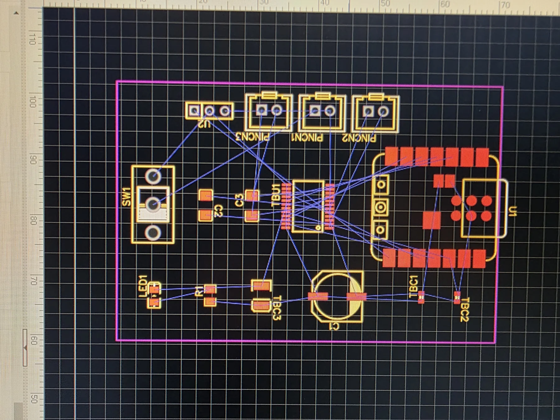
PCB layout
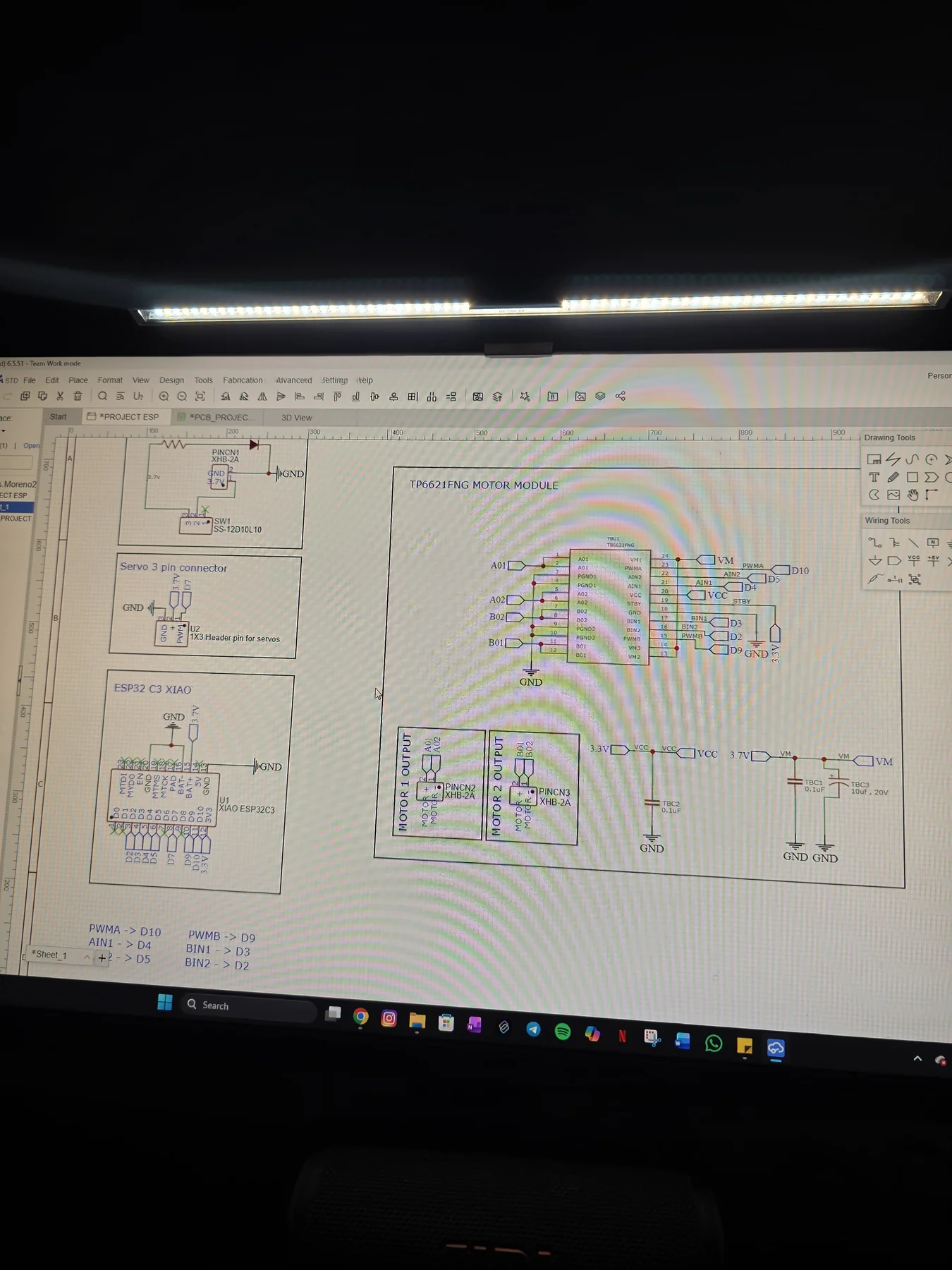
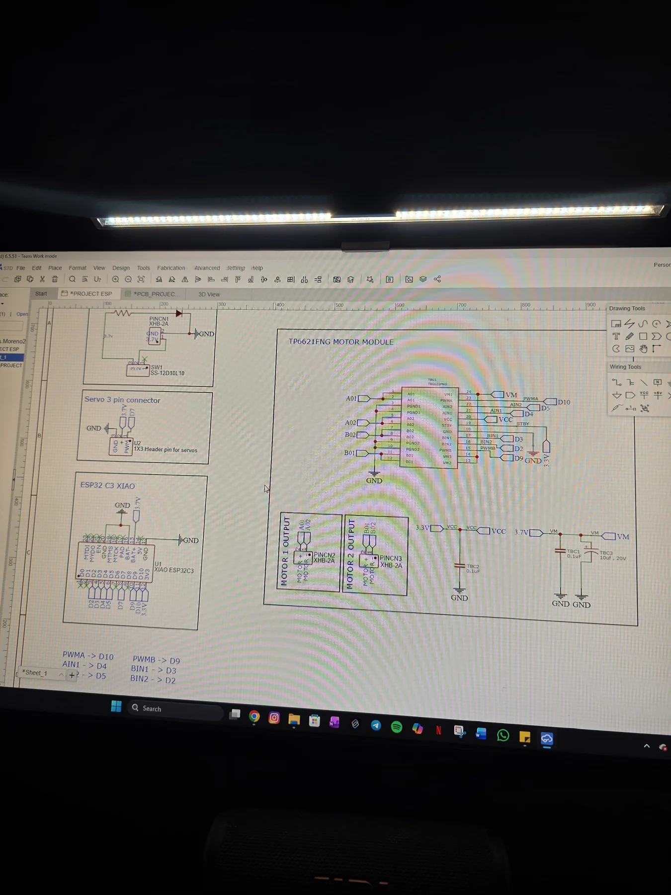
Schematic
Key Components
ESP32 (Car)
ESP32 (Remote)
TB6612FNG
Micro Servo
ESP-NOW
3D Chassis
Build Progress
✓
Concept
✓
CAD Design
✓
3D Print
✓
Wiring
✓
Firmware
→
PCB v2
What I Learned
  • ESP-NOW requires both devices on the same WiFi channel — there's no error message when it's wrong, just silence. Took me embarrassingly long to find in the docs.
  • Nobody tells you joystick ADCs are noisy. Without a dead zone around the centre (140 ADC counts on the throttle) the car creeps and twitches at rest. Spent an afternoon thinking the motor driver was faulty.
  • LEDC PWM in Arduino Core v3+ needs explicit channel assignment. The old analogWrite() approach silently stopped working — nowhere obvious in the changelog. Cost me a full day.
  • The XIAO ESP32-C3's built-in LiPo connector and onboard 3.3 V regulator eliminated an entire buck converter compared to v1. Battery connects directly to the XIAO, motor module, and servo — three connections, no conversion stage, one less thing to fail.
400 ms
Failsafe Cut-off
50 Hz
ESP-NOW Packets
20 kHz
Motor PWM
12K
Motor RPM
Chassis design, wiring, and firmware walkthrough below ↓

Project Overview

MCU
XIAO
Seeed ESP32-C3
Motor Driver
H-Bridge
TB6612FNG dual channel
Wireless
50
Hz ESP-NOW joystick packets
Build Status
Built
Assembled & bench-tested
At a Glance
TypePersonal project
My roleSolo: CAD, 3D printing, wiring, testing
CodeWritten with AI coding help
TimelineFeb – Mar 2026
SkillsMotor control · PWM · ESP-NOW · mechanical CAD
ToolsFusion 360 · Arduino C++ · Ender-3 S1 Pro → K1C · KiCad
StatusDriving · custom PCB in progress

A custom-designed, 3D-printed RC car — including the wheels — built around the Seeed Studio XIAO ESP32-C3. The chassis was modelled from scratch in Fusion 360 and printed in PLA: first on a Creality Ender-3 S1 Pro, then on a Creality K1C after bed-levelling and heated-bed problems on the Ender. Drive is handled by a DC 130 dual-shaft motor (3V–6V, 12,000 RPM, direct drive) controlled via a TB6612FNG H-bridge module, while steering uses an MG90 9 g metal-gear micro servo for Ackermann-style front-wheel control.

Wireless control runs over ESP-NOW between two ESP32-C3 boards — one on the car (receiver) and one on a breadboard transmitter: an ESP32-C3 SuperMini with two KY-023 analog joystick modules. Motor speed is controlled with LEDC PWM and joystick dead zones to keep low-speed movement stable.

The XIAO's built-in LiPo connector and onboard 3.3 V regulator eliminates the need for an external buck converter — the 3.7 V battery connects directly to the XIAO, motor module, and servo. A custom PCB to replace the protoboard wiring is in progress: the schematic is drawn in KiCad, and the board layout is the next step.
CAD Design & 3D Printing

The full chassis was designed parametrically in Fusion 360 as a multi-body assembly: main body, front steering knuckles, wheel mounts, motor bracket, servo bracket, and the wheels themselves — all 3D printed. Every component was designed to fit the micro servo and the DC 130 motor directly.

Phase 1 — Fusion 360 Design
Full chassis assembly with 4 wheels, motor mount, servo bracket, and electronics bay
The chassis was designed as a complete parametric assembly in Fusion 360. Components include: main chassis plate, front axle steering knuckles for Ackermann geometry, rear motor bracket sized to the DC 130 dual-shaft motor, servo bracket with horn clearance, four wheel mounts, and a top electronics bay for the PCB and LiPo cell. The wheels were also designed and printed, keeping the entire build self-made. All tolerances were set to account for FDM dimensional variation.
Phase 2 — 3D Printing (Ender-3 S1 Pro, then K1C)
PLA print with focus on front steering section and wheel cutout geometry
All chassis parts printed in PLA. I started on a Creality Ender-3 S1 Pro, but bed calibration and the heated bed kept causing problems, so I bought a Creality K1C and finished the parts on it. The front steering section with wheel cutouts required careful orientation to print without supports while maintaining dimensional accuracy for the servo horn interface. Layer height set to 0.2 mm for structural parts, 0.15 mm for steering knuckles requiring tighter tolerances. Parts were test-fitted before electronics installation.
CAD — Fusion 360
Design toolFusion 360 parametric
Chassis typeMulti-body assembly
Steering geometryAckermann front-wheel
Servo clearanceModelled for the MG90 micro servo
Motor mountDC 130 dual-shaft motor
3D Printing
PrinterEnder-3 S1 Pro → Creality K1C
MaterialPLA filament
Layer height (body)0.2 mm
Layer height (steering)0.15 mm
Support materialMinimised by orientation

Electronics & PCB Design

The electronics stack is built around the XIAO ESP32-C3 paired with a TB6612FNG H-bridge module. Supporting circuitry sits on a small protoboard: a power switch, red LED indicator, electrolytic capacitor for motor voltage spike suppression, and battery and motor connectors. A 100 nF ceramic capacitor is soldered across the motor terminals for brush noise suppression. A custom PCB replacing all of this is in progress in KiCad — the schematic was started in EasyEDA before being migrated to KiCad — targeting JLCPCB manufacture in the coming weeks.

TB6612FNG PinESP32-C3 GPIOFunction
PWMBD10Motor speed control (PWM / LEDC)
BIN1D4Motor direction bit 1
BIN2D5Motor direction bit 2
STBY3.3 VStandby — pulled high to enable driver
VM3.7 V LiPoMotor power supply (direct from LiPo, no regulation)
VCC3.3 VLogic power — from XIAO's onboard 3.3 V regulator
Servo SignalD7PWM steering (MG90 metal-gear micro servo)
Firmware — Motor Control
FrameworkArduino / ESP32-C3 Core
PWM APILEDC (ESP32-Arduino v3+)
Joystick dead zone140 ADC counts (throttle)
Direction controlBIN1/BIN2 + PWMB
Steering controlMicro servo via D7
WirelessESP-NOW P2P · 50 Hz packets
PCB — KiCad Design
Design toolEasyEDA → KiCad
Board layers2-layer (planned)
MCU footprintXIAO ESP32-C3
Motor driverTB6612FNG breakout
ConnectorsServo header · power switch
Manufacture statusDesign in progress — JLCPCB
Firmware

Written in Arduino C++ using the ESP-NOW API and the LEDC driver directly. The receiver auto-calibrates joystick centres on power-up (averages the first 60 readings) and requires the throttle to sit at centre briefly before arming — preventing a motor spin on connect. Motor PWM runs at 20 kHz on an 11-bit timer; servo outputs 50 Hz with pulse width constrained to 1000–2000 µs. A 400 ms failsafe cuts the motor if packets stop arriving.

Build & Assembly

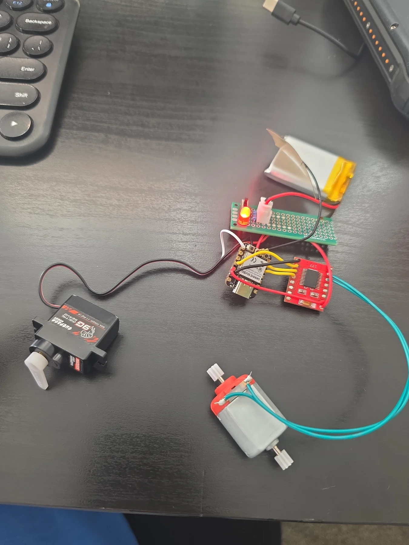
Phase 1 — Bench Testing
Motor, servo, and driver validated independently before chassis mounting
Before final assembly, each subsystem was bench-tested independently. The TB6612FNG motor driver was tested for bidirectional PWM control with the XIAO ESP32-C3 using both LEDC channels. The micro servo was checked for full range of motion on GPIO D7. Motor direction switching and speed control were verified across the full PWM range. All bench tests ran from LiPo power through a bench PSU current limiter for safety.
Phase 2 — Chassis Assembly
3D-printed chassis assembled with motor, servo, and wheel mounts
All 3D-printed chassis parts assembled in sequence: rear motor bracket press-fitted and secured, front steering knuckles inserted with press-fit axle pins, micro servo mounted in its bracket with horn connected to the steering linkage, and all four wheels attached. Fit and full steering range were checked before installing any electronics.
Phase 3 — Electronics Mounting
XIAO ESP32-C3, TB6612FNG breakout, and LiPo mounted to chassis top plate
Electronics mounted to the chassis top plate. XIAO ESP32-C3 positioned for USB-C access, with its antenna sticker adhered to the chassis exterior for unobstructed RF. TB6612FNG module wired to all motor and GPIO pins per pin mapping table. LiPo cell positioned for centre-of-gravity balance. Wireless control tested end-to-end with the ESP-NOW transmitter — car drives and steers correctly in both directions.

Demo

Driving test — forward & reverse
Steering — left & right lock
Full drive — steering and throttle
← Large RC Car ⌂ Portfolio RetroDS →