Project overview
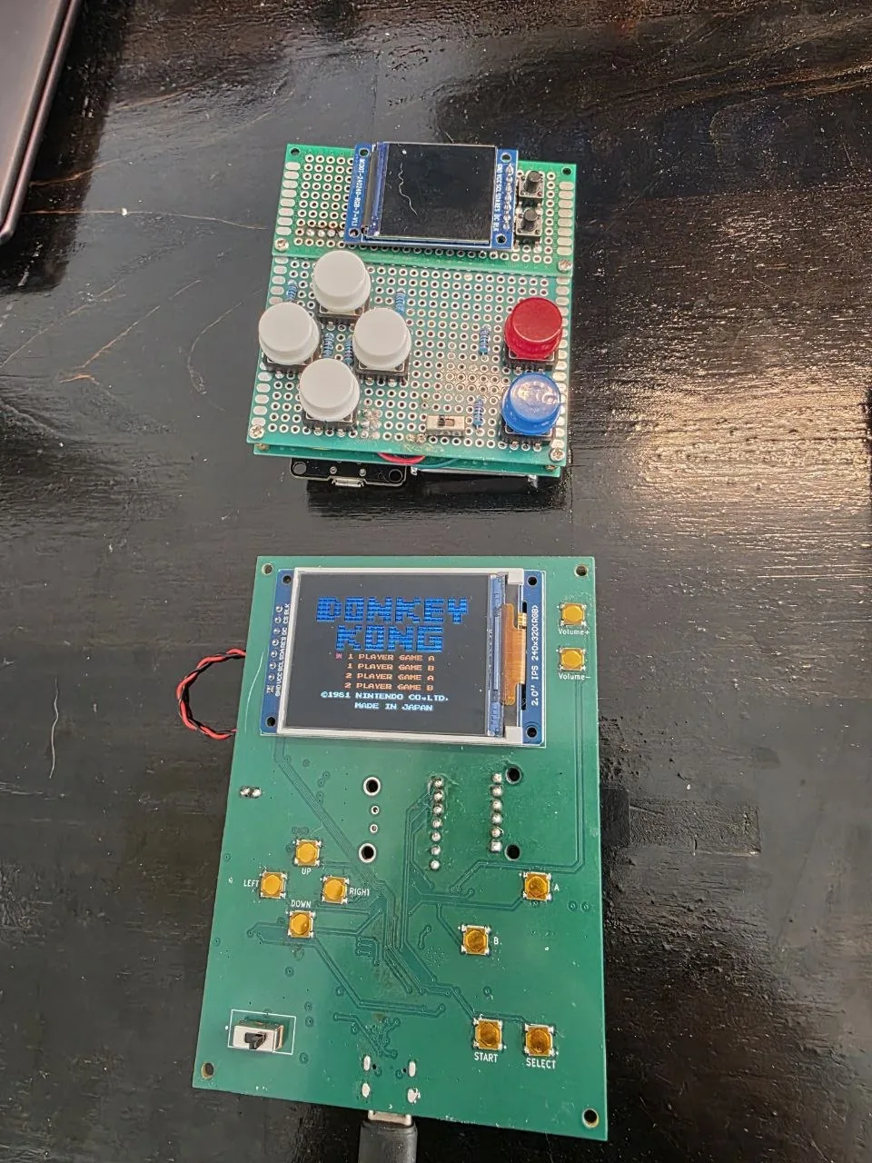
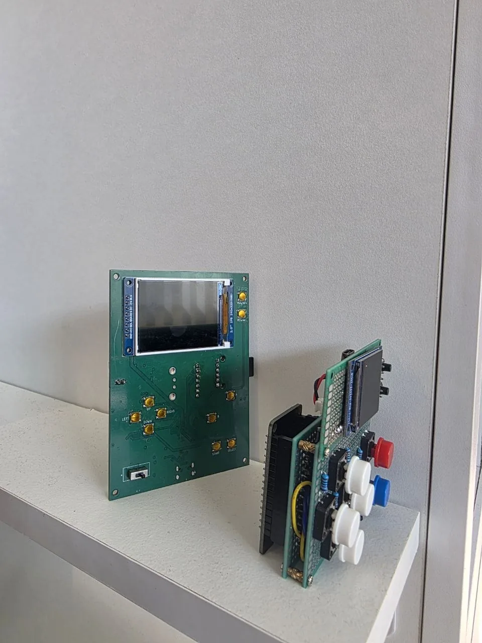
RetroDS is a handheld NES emulator I've been building on an ESP32. Version 1 was a hand-soldered perfboard — a classic ESP32, a 240×240 display, ROMs from an SD card, USB power. It ran games, but the wiring was fragile, there was no sound, and there was no way to keep save-game progress.
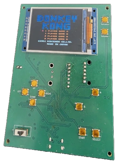
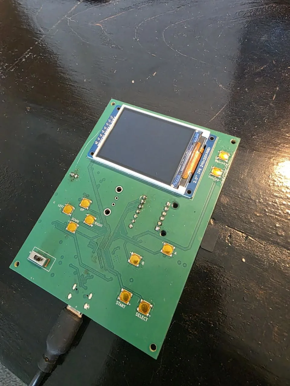
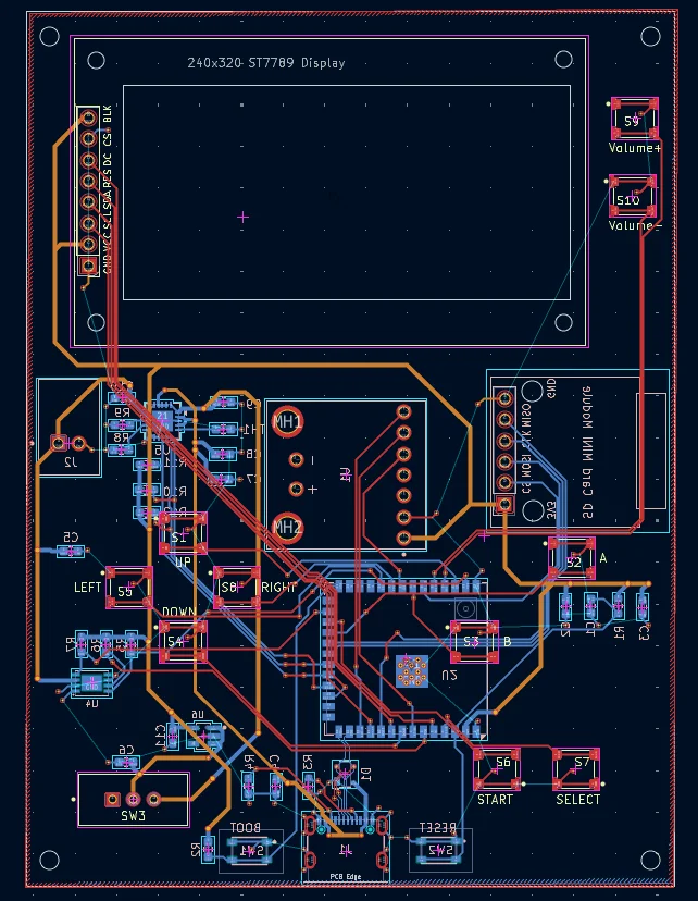
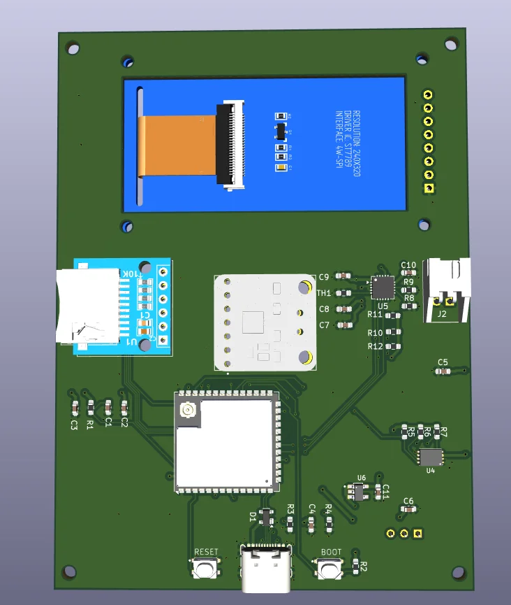
Version 2 is a custom 4-layer PCB. The emulator core (the open-source NESCAT emulator by Nathalis, GPL-3.0) carries straight across; almost everything around it is new hardware: an ESP32-S3 with native USB-C, a Li-ion charger with load sharing, an I²S audio amplifier, a dedicated SD interface, and silk-screened controls on the board itself.
This page covers the part that isn't the schematic: getting the assembled board to work. Two faults had to be found with a multimeter before a single line of firmware mattered, and then the firmware needed a rewrite for the new silicon.
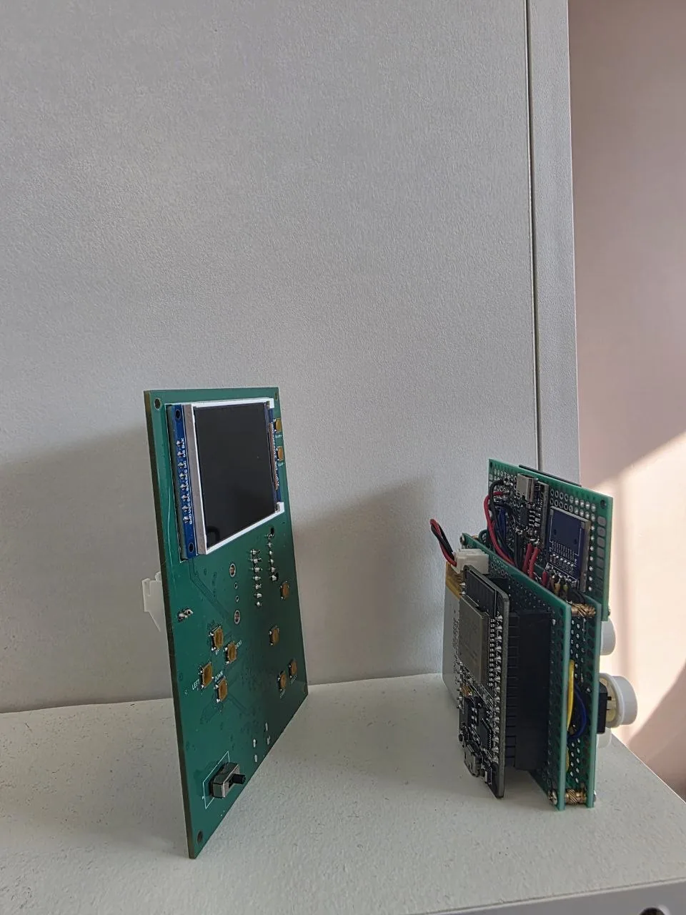
What changed from v1
| Subsystem | v1 — perfboard | v2 — custom PCB |
|---|---|---|
| MCU | ESP32-WROOM-32 (D1 mini board), USB-UART bridge chip | ESP32-S3-WROOM-1U-N8 — native USB, 8 MB flash |
| Display | ST7789 240×240, TFT_eSPI library | ST7789 240×320, LovyanGFX (DMA) |
| Audio | none | MAX98357A I²S class-D amp + 4Ω 3W speaker, 15-step volume |
| Power | LiPo 3.7 V cell, TP4056 USB-C charger + IP5306 boost (2 chips) | MCP73871 load-sharing charger + AP2112K 3.3 V regulator, USB-C |
| SD card | bit-banged soft-SPI | dedicated hardware SPI bus, hot-insert detection |
| Save games | none | battery-backed SRAM → /NES/<rom>.nes.sav, autosave |
| ESD / protection | none | ESD-protection footprint on the USB data lines (D1, left unpopulated) |
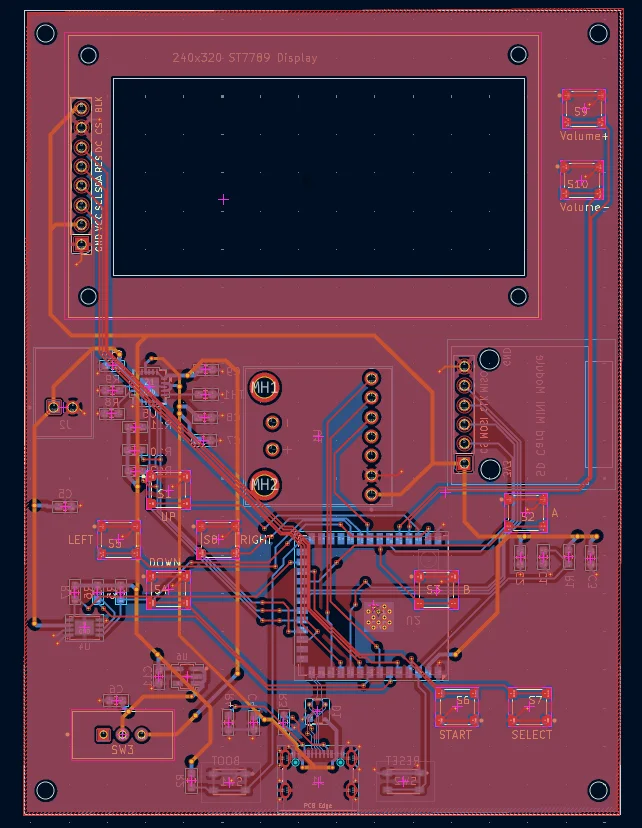
| Interconnect | point-to-point hand-run wiring | routed 4-layer board, GND plane, silk-screened controls |
Hardware architecture
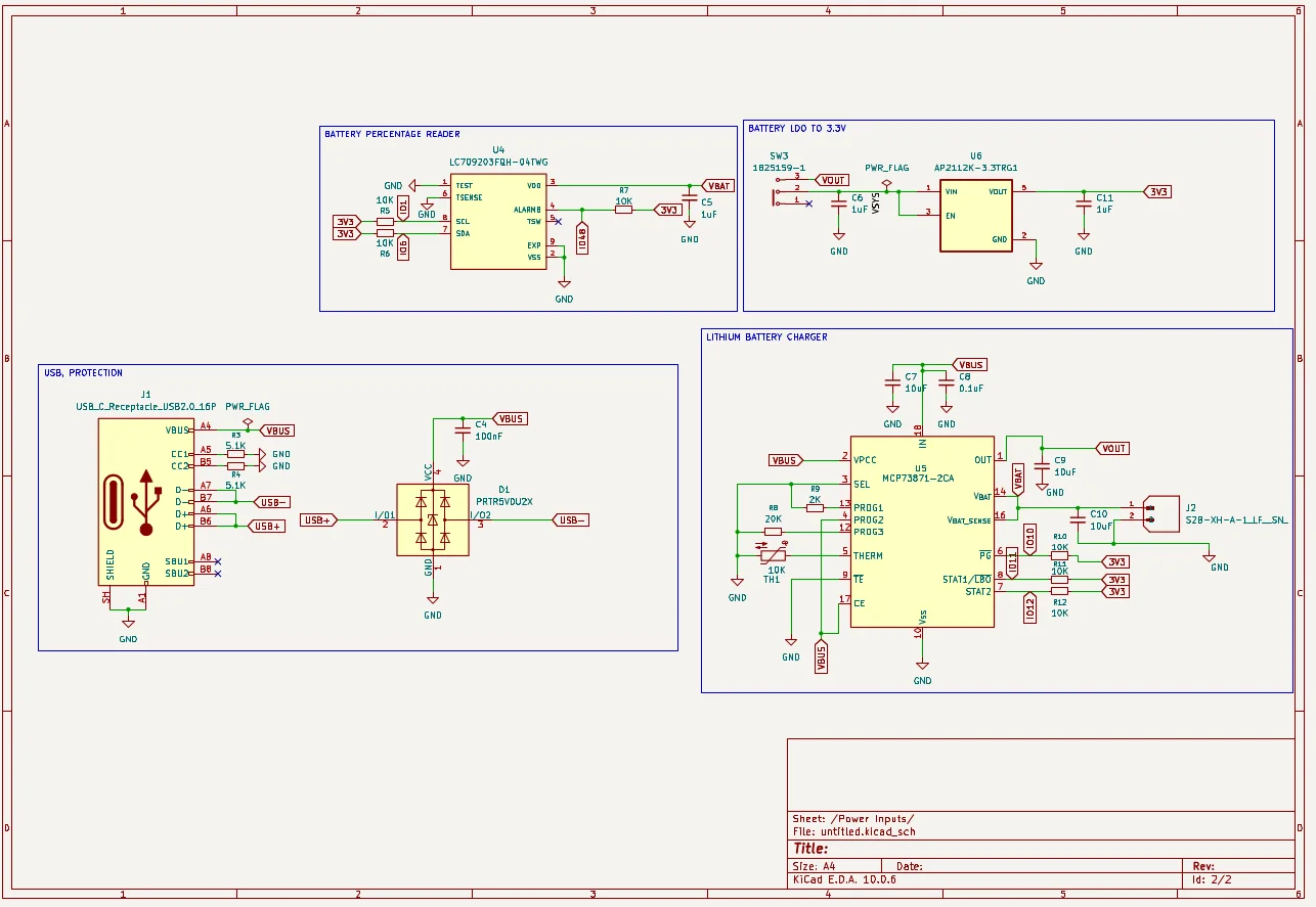
The power path is a load-sharing design: USB VBUS → MCP73871 → VOUT → SW3 → VSYS → AP2112K LDO → 3V3. With USB connected the charger runs the system and tops up the cell, giving the system-load priority so the total never exceeds the USB current limit; unplug USB and it hands over to the battery through an internal ideal-diode MOSFET. The battery charges whether the power switch is on or off — the charge path doesn't pass through it.
The display and the SD card sit on separate SPI peripherals (SPI3 and SPI2) so neither blocks the other. All buttons are active-low to internal pull-ups.
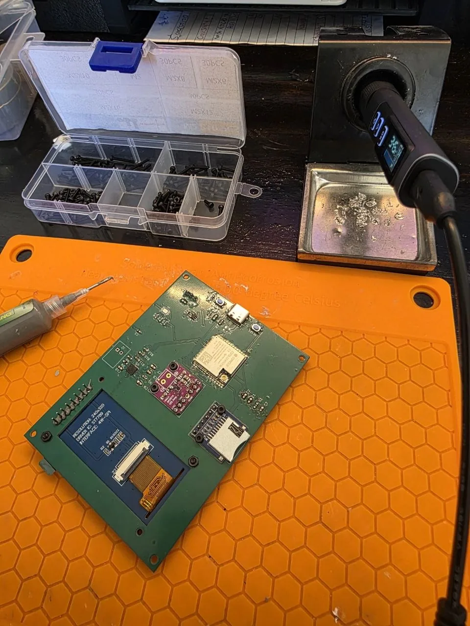
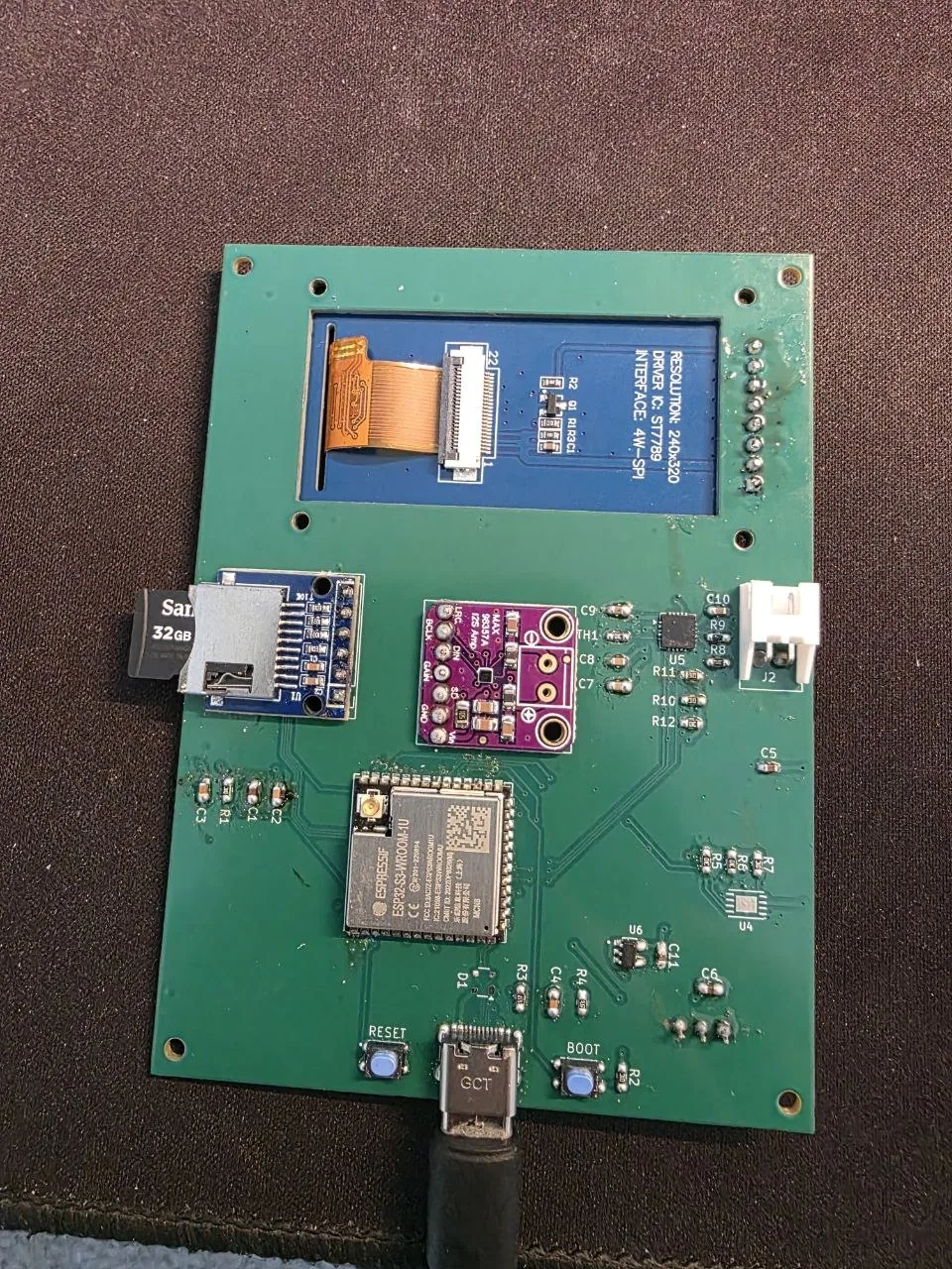
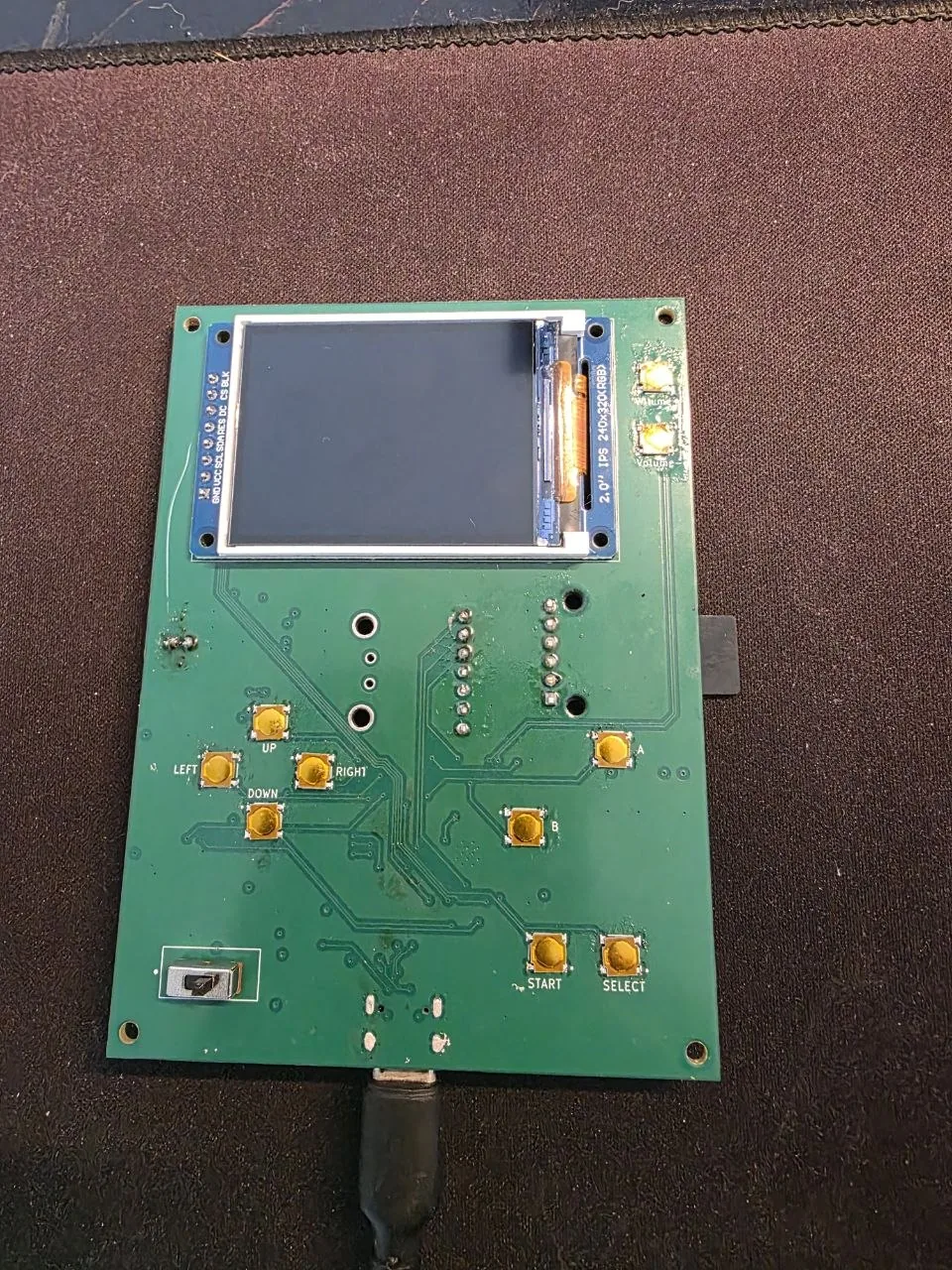
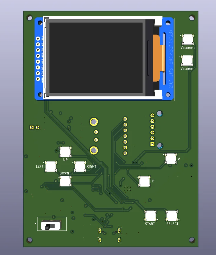
Component placement was also an assembly decision. Nearly everything that needs a hot-air station or a hotplate — the ESP32-S3 module, the MCP73871 QFN and the SOT-23 AP2112K regulator — is on the back, along with the plug-in MAX98357A amp and SD modules. The front carries only the buttons (small SMD tactile switches) and the through-hole slide switch, which hand-solder fine with an iron and don't fight for space against silicon. That split meant soldering the back first, while the board was easiest to handle and before any tall components were in the way, then finishing with the buttons — and it leaves the front face mechanically clean so the button caps sit flush against the 3D-printed case.
romdata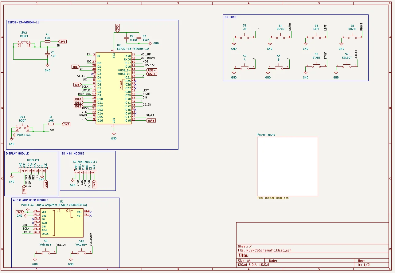
Bring-up — the board wouldn't enumerate
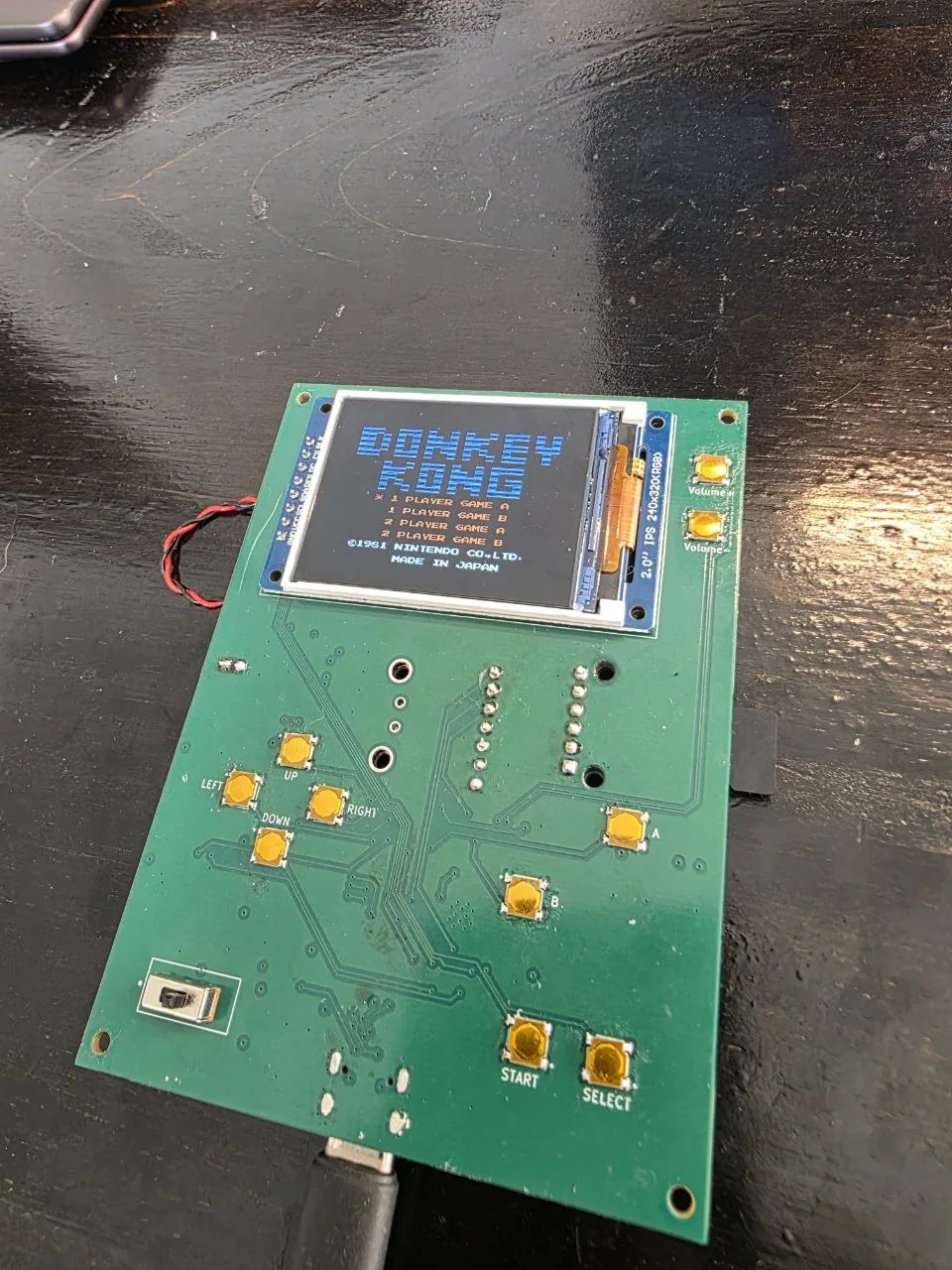
First power-up: the host would see a USB device attach and drop it a second later, repeating on a fixed cycle. dmesg showed the descriptor read failing (error -71) and /dev/ttyACM0 appearing and vanishing every couple of seconds. No serial output ever arrived.
Rather than assume a bad solder joint on the USB connector, I read the cycle: the ESP32-S3's USB peripheral re-enumerates on every chip reset, and a fixed ~2 s period means the chip is resetting in a loop — a brown-out. That moved the problem from "USB / firmware" to "power path", so I measured it, one node at a time, with USB connected:
The MCP73871 is a 20-pin QFN; its exposed centre pad carries the ground return and the charge-current heat. An unwetted centre pad or an open pin on the input/output side leaves it non-conducting. I reflowed the pad and the IN/OUT pins — VOUT went to ~5 V, the 3.3 V rail came up, and the board enumerated and took a firmware flash.
Bring-up — a hidden 3.3 V-to-ground short
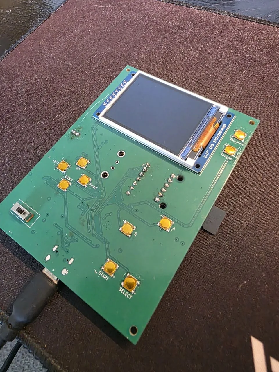
With USB working I fitted the display, SD and volume-button modules — and the board went dark again. This time the 3.3 V rail measured a dead short to ground. Under magnification the PCB was clean; nothing was bridged.
A continuity beep is not a short test — the display bus alone carries roughly 10 µF, which beeps briefly while the capacitors charge. So I measured resistance instead: 3V3 to GND in ohms, both probe directions, watching whether the reading settled.
Two smaller issues fell out of the same session. The SD card mounted nothing and SdFat reported "check SD format" — the card responded fine over SPI but was formatted NTFS; reformatting FAT32 and restoring the ROMs to /NES/ fixed it. And D1, the USB ESD array, was deliberately left unpopulated during bring-up as a check — the data lines pass straight through its footprint, so leaving it off first confirmed the USB routing itself was good, independent of the part. USB enumerated and ran fine without it, so it's stayed unpopulated: no functional loss, just less transient/ESD margin than the design allows for.
Firmware — the rewrite for the S3
The v1 firmware assumed the classic ESP32 and TFT_eSPI. On the ESP32-S3 with the current Arduino core that library crashes on init() — a known incompatibility. The display layer was re-done, and several things v1 never had were built in.
On tooling: I worked through this rewrite with Claude, an AI coding assistant, as a pair-programmer — adapting the v1 code to the S3's APIs, working out the LovyanGFX and I²S configs, and using it as a second reader in code review. The hardware fault-finding, the design choices, and the testing on the bench were mine; every AI-suggested change was read, understood and checked on the target board before it stayed in.
micros() deadline to NES_REFRESH_RATE — 60 Hz NTSC, to match the ROM set (the core it forked from defaulted to PAL/50, which ran these US and Japanese titles ~17% slow). The video task also yields after each blit so it stops starving the emulator of internal-RAM bandwidth — there's no PSRAM on this module./NES/<rom>.nes.sav — loaded on start, written on exit, and autosaved every 3 minutes and the moment the charger reports a low battery.CHARGING / FULL / BATTERY / LOW BATT, shown in the menu and as an in-game low-battery banner.while(1) lock-ups on recoverable errors — a bad ROM, an unsupported mapper, a missing /NES/ folder. All are now an on-screen message and a return to the menu.Results & what's left
Enclosure & final build
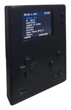
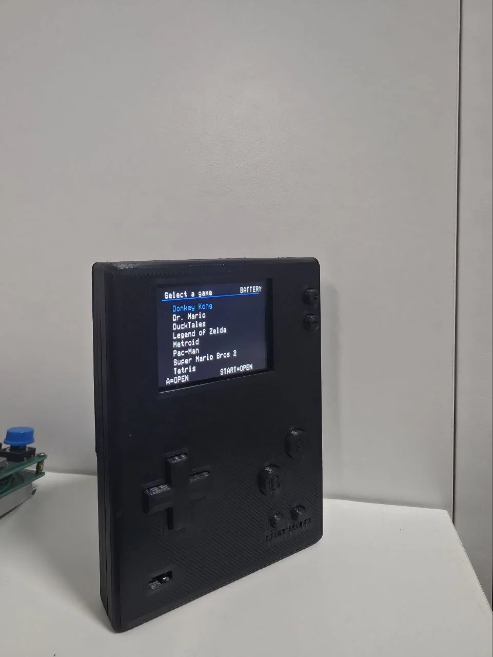
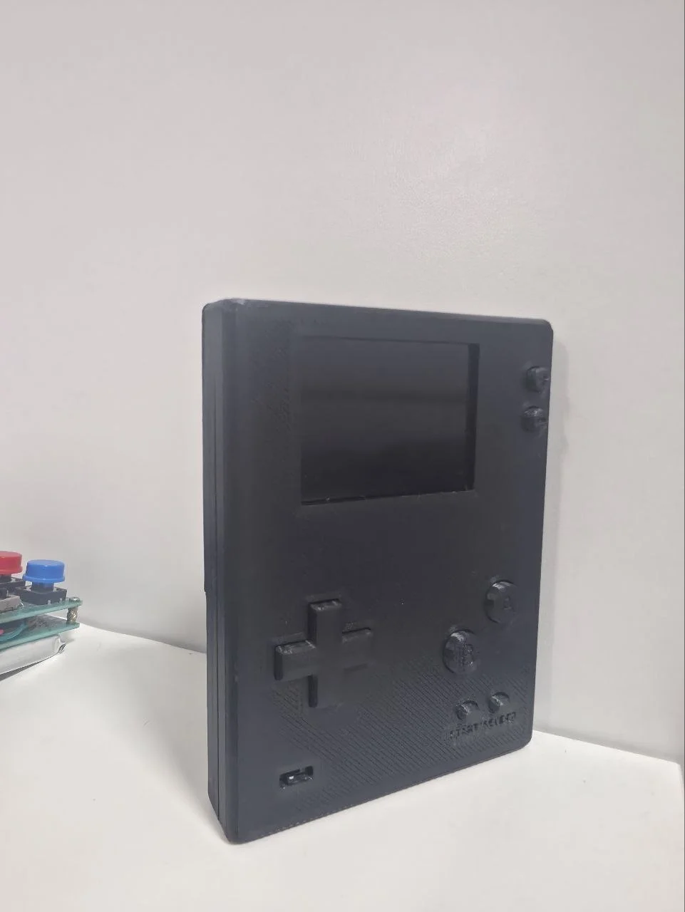
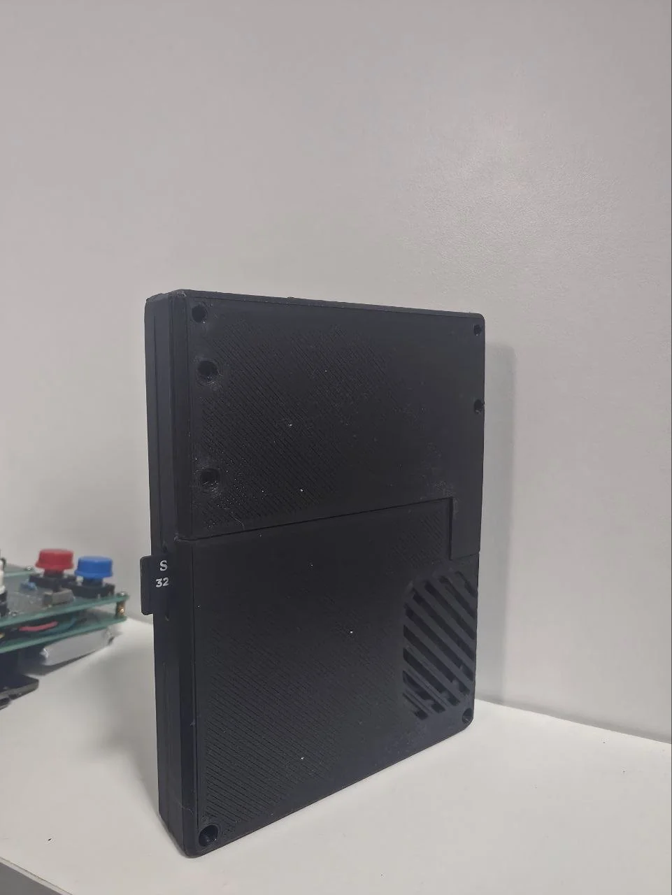
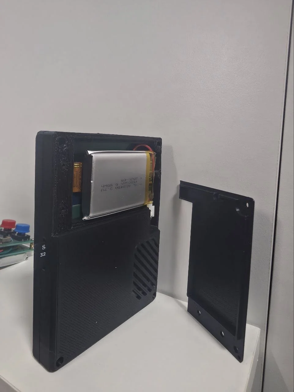
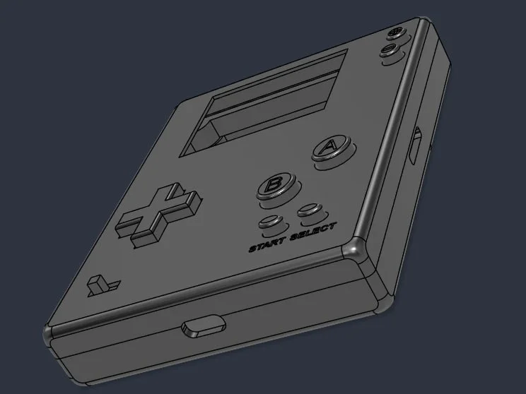
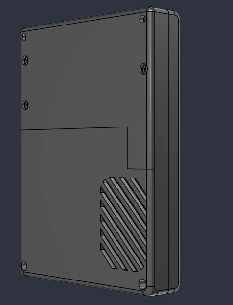
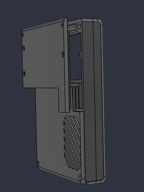
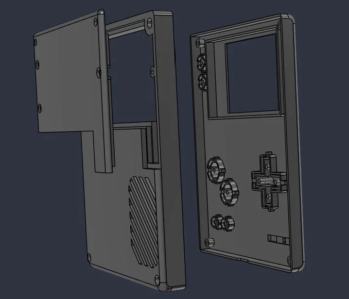
The board was designed to fit a 3D-printed handheld shell. The case is printed, the PCB seats in it, and every button presses cleanly through the front face. It runs as a self-contained portable — a 3.7 V 1500 mAh Li-ion pouch cell, speaker, SD and screen all on the one board, no bench leads.
The code
v1 (perfboard) and v2 (this board) share the emulator core and are kept in separate folders with a code map. Key v2 snippets — the display config, the frame blit, the save path, the charge-status decode — are in the 📋 Code Notes panel (top right).
One quirk cost an afternoon: the Arduino build step auto-generates function prototypes and hoists them above your typedefs and enums. Any function that took the new enum charge-state type got a prototype placed before the type existed, and the sketch wouldn't compile. The fix was to drop the enum for plain integer constants and pass buffers by raw pointer — undramatic, but the kind of thing that only bites once you know to expect it.
v2 firmware — NES EMULATOR CODE/NesCat/: NesCat.ino · LGFX_RetroDS.h · v2_pins.h · partitions.csv · BUILD_v2.md
v1 firmware (archived) — NES EMULATOR CODE/v1-perfboard/
Full repository link will be added when it's public.