Engineering Design Portfolio — Robotics & Embedded Systems

SO-101 Robotic Arm

Leader-Follower Teleoperation · 12× STS3215 Servos · ESP32-C3 Wireless Upgrade · Jun–Jul 2026
TheRobotStudio SO-101 12× Feetech STS3215 Servos LeRobot Teleoperation ESP-NOW Wireless · ~100 Hz
2× ESP32-C3 Super Mini 3D-Printed Links Working — Wireless Teleop
Result TheRobotStudio's SO-101 (built from their SO-ARM100 repo) is an open-source design (Apache-2.0) — the parts were sourced, both arms 3D printed and assembled, and everything calibrated through LeRobot. The one piece that isn't in the official repo: two ESP32-C3 boards added afterward to mirror all 6 joints wirelessly over ESP-NOW, cutting the USB tether to the PC.
TheRobotStudio/SO-ARM100 → Apache-2.0 · open-source hardware & software
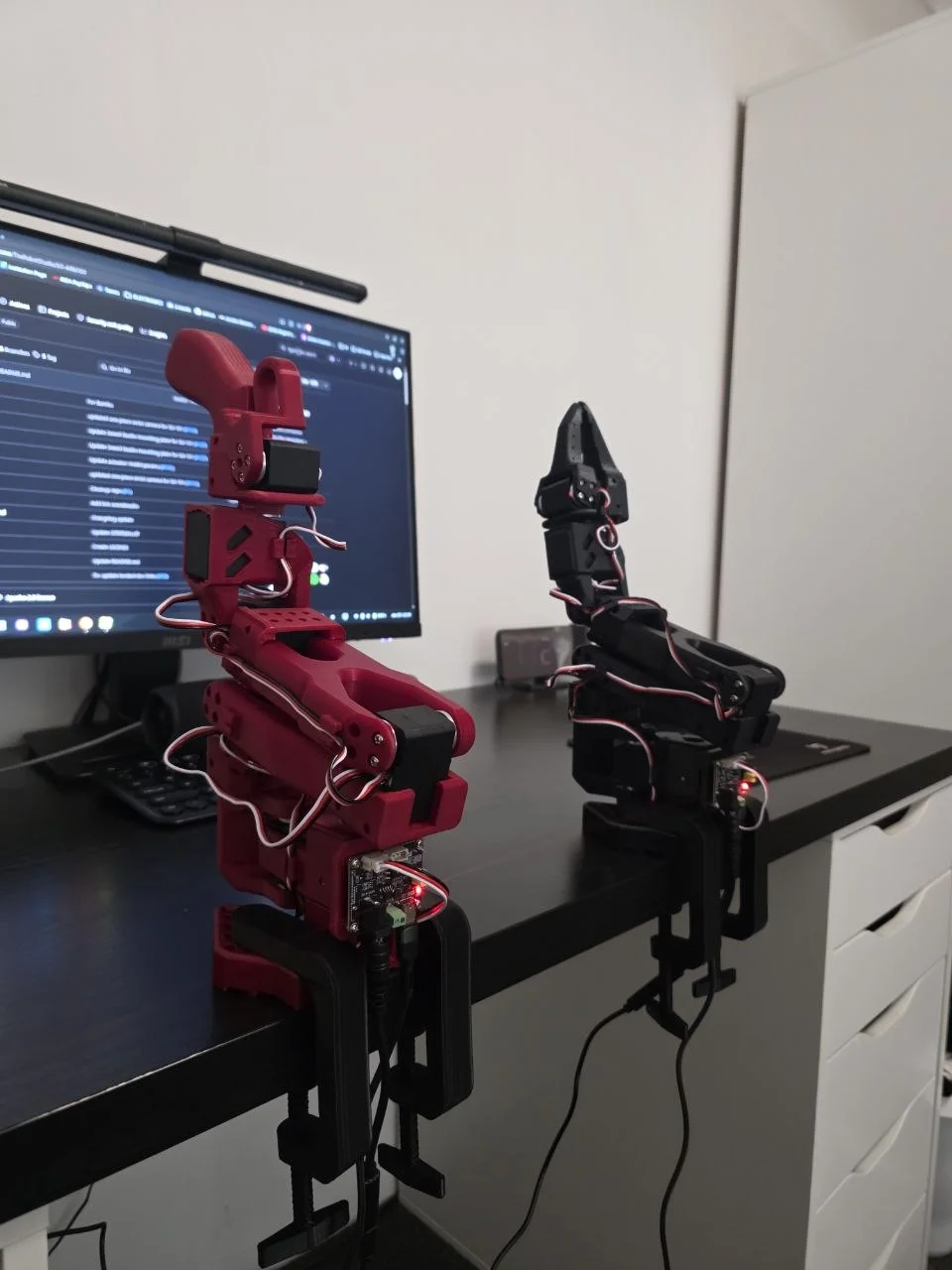
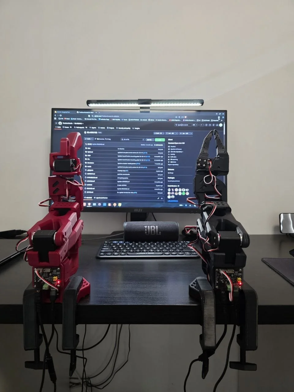
Leader (red) and follower (black) arms, desk-clamped, monitor with the SO-ARM100 repo in the background

Picked the SO-101 over the pricier AM-ARM200 mostly on servo cost — same LeRobot-compatible teleoperation, cheaper parts. Sourced the 12 STS3215 servos as an Alibaba bundle, calibrated both arms in LeRobot, and had it working over USB in a day. The real project started after that: a cheap clone motor-controller board turned out to pass input voltage straight through to the servos with zero regulation, and the first attempt to wire an ESP32 directly onto the servo bus's data line fought the board's own direction-switching circuit. Routing through the board's dedicated UART header instead — and moving to two ESP32-C3 Super Minis talking ESP-NOW — is what finally cut the USB cable for good.

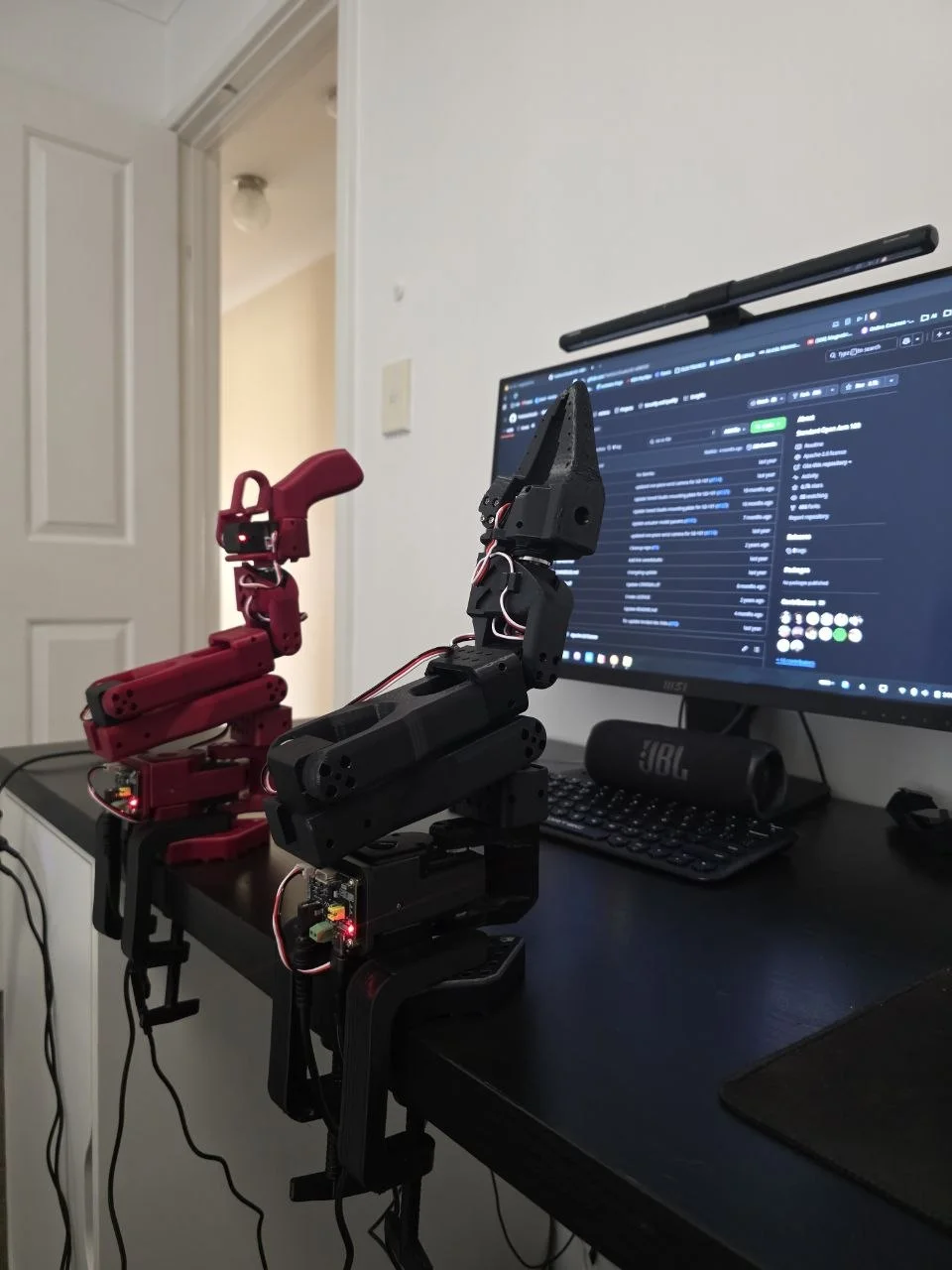
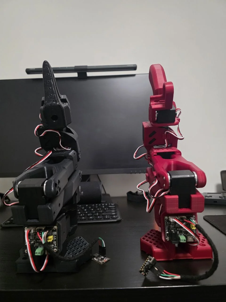
Leader and follower arms, side profile
Leader (red) & follower (black) — desk-clamped, powered and idle
Both arms side profile
Both arms front view
Arms clamped to desk
Follower arm front
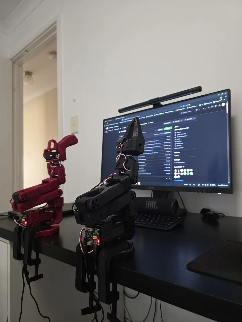
Both arms facing monitor
Key Components
STS3215 ×12
ESP32-C3 (Leader)
ESP32-C3 (Follower)
ESP-NOW
LeRobot
3D Print
Build Progress
✓
Sourcing
✓
Assembly
✓
LeRobot Calib
✓
USB Teleop
✓
ESP-NOW Wireless
→
Data Collection
What I Learned
  • The AliExpress clone motor-controller board ("Bus Servo Adapter A") passes input voltage straight through to the servo bus with no regulation. The STS3215 needs 4.5–8.4 V; the board accepts 9–12.6 V input. Only safe pairing: a dedicated 7.4V supply — not the 12 V or 5 V I had lying around.
  • My first attempt tapped the servo bus data pin directly, in parallel with each arm's daisy chain. It fought the board's own direction-switching circuit and dropped packets constantly. Going through the board's dedicated UART header (jumper set to UART mode) fixed it instantly — the board already handles half-duplex switching internally.
  • arduino-esp32 v3.3.10 changed the ESP-NOW callback signatures without much warning: receive callbacks now take esp_now_recv_info_t* instead of a raw MAC pointer, send callbacks take wifi_tx_info_t*. Every ESP-NOW example online still shows the old signatures.
  • noInterrupts() does not protect against the FreeRTOS WiFi task pre-empting your main loop — that's not a hardware ISR. Fixed it with a volatile double-buffer instead: the receive callback just copies the packet and flips a flag; the main loop reads it out on its own time.
12
STS3215 Servos
12 B
ESP-NOW Packet
100 Hz
Joint Update Rate
6 DOF
Per Arm
Sourcing, LeRobot setup, and the wireless ESP32-C3 upgrade below ↓

Project Overview

Servos
12×
Feetech STS3215 C001, 7.4V
Control MCU
ESP32-C3
×2, Super Mini form factor
Wireless Link
ESP-NOW
Peer-to-peer, no router or PC
Build Status
Working
Wireless teleop confirmed end-to-end

The SO-101 is TheRobotStudio's open-source leader-follower robotic arm (Apache-2.0) — the current version of their SO-ARM100 design — built for the Hugging Face LeRobot ecosystem — you physically move the leader arm, and the follower mirrors it in real time, the standard way to collect teleoperation data for training robot learning policies. It was chosen over the pricier AM-ARM200 mainly on servo economics — full comparison in the sourcing section below.

Everything through this point is stock SO-101: the 12 Feetech STS3215 servos and both motor-controller boards were bought as parts, the arm links were 3D printed from TheRobotStudio's original files, and both arms were assembled and calibrated through LeRobot's Python tooling — homing offsets and safe position limits get burned straight into each servo's EEPROM. The one part that isn't stock: the desk clamps, custom-modelled from scratch — more on that below.

What isn't in the official repo is the wireless link. The arm pair worked over USB from day one; built on top of that are two ESP32-C3 Super Mini boards that read the leader's joints and mirror them to the follower over ESP-NOW, no PC in the loop. Full breakdown in the Wireless Upgrade section below.
At a Glance
TypePersonal project
My roleSourcing, printing, assembly, calibration; designed the desk clamps and the wireless link
CodeESP-NOW link code written with AI coding help
TimelineJun 2026 – present
SkillsServo bus protocols · ESP-NOW · calibration · fault-finding
ToolsLeRobot (Python) · Arduino C++ · Fusion 360 · MuJoCo
StatusTeleop working · dataset recording next
Built On (Credits)
Arm designSO-101 by TheRobotStudio (Apache-2.0)
Robot softwareLeRobot (Hugging Face)
ServosFeetech STS3215
Simulation modelOfficial SO-101 MuJoCo model (TheRobotStudio)
My additionsDesk clamps, ESP32-C3 wireless link, dual-gripper setup

Servos, Sourcing & Mechanical

The SO-101 has one real drop-in constraint: the Feetech STS3215 serial bus servo. It's a proprietary 45.2 × 24.7 × 35 mm form factor with position feedback over a single-wire half-duplex bus — no cheaper PWM servo (MG996R and similar) can substitute, because those have no feedback and can't support LeRobot's teleoperation or policy-learning pipeline. The correct variant is the C001: 7.4 V, 19.5 kg·cm torque, 1:345 gear ratio. The 12 V/30 kg C018 variant exists but is more expensive and isn't what the official BOM specifies.

Building a cheaper DIY equivalent — DC motor, gearbox, AS5048 magnetic encoder, custom driver PCB — was seriously considered and ruled out: at roughly $20–30 per joint plus hours of engineering per axis, it lands close to the STS3215's $13.89/unit Alibaba price without any of the reliability or drop-in compatibility.

Servo — Feetech STS3215 (C001)
Voltage7.4 V
Torque19.5 kg·cm
Gear ratio1:345
Dimensions45.2 × 24.7 × 35 mm
InterfaceHalf-duplex serial bus, position feedback
Servos per arm6 (12 total, two arms)
Sourcing Decision
Official BOM estimate~$230 (two-arm set)
Chosen: Alibaba bundle$289.80 (12 servos + board + cables)
AliExpress (separate)~$325
Amazon / eBay 12-pack~$285–312
Arm links3D printed, TheRobotStudio's STL files
Desk clampsCustom-designed, PETG
Alternative ConsideredWhy Ruled Out
AM-ARM200~$380 full kit vs ~$230 — 3× STS3095 servos at ~$50 each drive the cost up
Moss Robot ArmsSame servos, same cost, and being deprecated in favour of SO-ARM100
Koch v1.1Uses Dynamixel servos — notably more expensive per joint
MG996R-based armsNo position feedback — can't support LeRobot teleoperation or policy training
DIY servo (DC + encoder)~$20–30/joint plus hours of engineering per axis — lands at the STS3215 price anyway
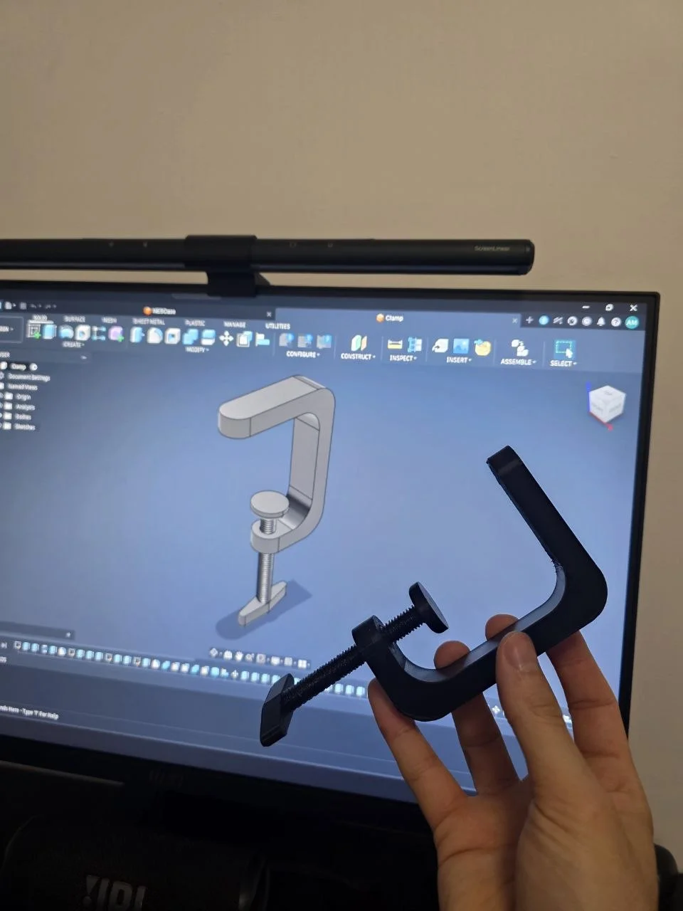
Fusion 360 model of the desk clamp on screen, next to the printed PETG part held in hand
Desk clamp — custom-designed, not part of the SO-ARM100 repo
The one structural part that isn't printed from TheRobotStudio's files. Modelled from scratch in Fusion 360 and sized to survive the clamp screw's pinch force against the desk edge without cracking under the arm's own weight. Printed in PETG — not the PLA+ TheRobotStudio's own build guide recommends — for the extra toughness under that sustained clamping load, with a hexagonal infill pattern for added rigidity.

LeRobot Software & Calibration

Both arms are brought up and calibrated through Hugging Face's LeRobot Python library. A dedicated conda environment (lerobot) was set up with the Feetech servo backend, and both controller boards were found on /dev/ttyACM0 (one at a time, since both boards enumerate identically). Motor IDs were assigned 1–6 on each arm, followed by LeRobot's guided calibration routine, which walks each joint through its range and burns homing offsets directly into servo EEPROM — no recalibration is needed later on the ESP32 firmware, since the offsets travel with the hardware.

Clone motor-controller board — voltage pass-through
The board bought alongside the servos was an AliExpress clone ("Bus Servo Adapter A"), not the official Waveshare board it was modelled on. It turned out to pass input voltage straight through to the servo bus with zero regulation — input range 9–12.6 V in, same voltage out to the servos. The STS3215 wants 4.5–8.4 V (ideally 7.4 V). Fix: power the board from a dedicated 7.4 V supply — not the 5 V or 12 V supplies already on hand. Teleoperation was blocked for a stretch waiting on a second 7.4 V supply for the leader arm.

The Wireless Upgrade

USB teleoperation works, but tethers both arms to a PC and to each other's cable runs — awkward for anything beyond a desk demo. The goal was to cut the cable and mirror the leader arm's 6 joints to the follower wirelessly, with low enough latency that it still feels like direct control.

Phase 1 — PC-Tethered Teleoperation (LeRobot)
Baseline: both arms on USB, driven directly by LeRobot on a PC
The starting point and the one LeRobot ships out of the box: leader and follower both plugged into a PC over USB, with lerobot-teleoperate reading the leader's joint positions and writing them to the follower in a tight Python loop. This confirmed both arms, all 12 servos, and the calibration data were correct before touching any custom firmware.
Phase 2 — First Wired Attempt: Direct Data-Pin Tap
Tapping the servo bus data line directly caused interference with the board's own direction circuit
The first idea was to tap the half-duplex data line of each arm's servo daisy chain directly from a GPIO pin. In practice this fought the motor controller board's own internal direction-switching circuit — the board expects to be the one driving that line's direction, and having an external GPIO also toggling it caused corrupted reads and dropped packets. Fix: go through the board's dedicated UART header instead (with its jumper set to UART mode), which lets the board handle half-duplex direction switching internally — the ESP32 just talks standard UART TX/RX to the header, no data-pin trickery required.
Phase 3 — ESP32-C3 Super Mini Wireless (ESP-NOW) — Working
Two ESP32-C3 Super Mini boards, one per arm, mirror joint positions wirelessly at 100 Hz
The final architecture: a leader board reads all 6 STS3215 positions from the leader arm over UART (1 Mbps, half-duplex) and sends them as a 12-byte ESP-NOW packet. A follower board receives that packet, clamps each joint to safe position limits pulled straight from the LeRobot calibration JSON, and sync-writes all 6 goal positions to the follower arm in one broadcast instruction. Each arm was bring-up tested standalone first — a small servo_test sketch reads and wiggles all 6 joints, confirming the ESP32 can talk to that arm's servos before any ESP-NOW code goes near it. First-time pairing: flash the follower sketch first, read its MAC address off the Serial Monitor, paste it into the leader sketch, then flash the leader. Confirmed working end-to-end — moving the leader arm by hand drives the follower in real time with no perceptible lag.
Confirmed Leader arm mirrors to follower arm wirelessly at 100 Hz — no PC in the loop, no router.
Phase 4 — Two Grippers, Back to USB for Training — Sep 2026
Leader arm given a real gripper; both arms on USB so LeRobot can record
To train a policy, LeRobot's recorder has to log both arms on the PC, which the ESP-NOW mirror can't do, so the arms went back to USB. The leader's passive handle was swapped for a printed copy of the follower's gripper, making both arms identical, and both were recalibrated. Two faults came up and were fixed: the follower board found no servos (a loose connector at the board, found by swapping boards and servo chains between arms), and one leader joint made the follower snap to its opposite limit (the encoder's wrap point sat inside the joint's travel because the joint wasn't centred during calibration; recalibrating at the true midpoint fixed it). Teleop is smooth again, and a first test episode recorded to disk correctly.

Electronics & Wiring

Both boards are wired identically. The motor controller board is powered from an external 5 V supply, and the ESP32-C3 talks to it over the board's UART header rather than the raw servo data line.

SignalESP32-C3 GPIOFunction
Board 5V5V pinMotor controller board power (external 5V supply)
Board GNDGNDCommon ground
Board RX (UART header)GPIO 4ESP32 TX → board RX, jumper set to UART mode
Board TX (UART header)GPIO 3Board TX → ESP32 RX
Power sequencing — never bridge board 5V and USB 5V
The ESP32-C3 is powered from USB only while programming, and from the board's 5V rail once standalone. Connecting both simultaneously risks backfeeding one supply into the other — always disconnect USB before powering from the board, and vice versa.
Servo Bus Protocol
Baud rate1,000,000 (1 Mbps)
Wire modeHalf-duplex, single-wire
Read instructionSTS 0x02 — present position
Write instructionSTS 0x83 — sync write, all 6 in one packet
Loop rate100 Hz (10 ms period)
ESP-NOW Link
Payload6× int16_t positions, 12 bytes
PairingStatic MAC address, unencrypted
LagNone noticeable by hand (not timed)
Safety clampFollower constrains to LeRobot calibration limits
BoardESP32C3 Dev Module, USB CDC On Boot: Enabled
Firmware

Both sketches are plain Arduino C++ using esp_now.h and the STS servo protocol implemented by hand over HardwareSerial — no external servo library. The follower's receive callback runs inside the FreeRTOS WiFi task, so it only copies the incoming packet into a buffer and flips a flag; the main loop does the actual servo write on its own schedule, avoiding any work inside the callback itself.

Demo

Both arms powered, wireless link active
Leader & follower extended — full range of motion
Wireless teleoperation — moving the leader by hand, follower mirrors live
← ESP32-S3 Dev Board ⌂ Portfolio