First Ever Project · 2025

Exhaust Cutout
Controller

Arduino Nano · MD13S Cytron · Fusion 360 · 12V Car Power
✓ Installed & Working Arduino Nano (ATmega328P) Fusion 360 Enclosure First Project

My first hardware project — I wanted exhaust cutout valves on a VW Golf Mk6 and decided to put an Arduino in the middle of it, which in hindsight added complexity for no real benefit. But the enclosure came out well, the firmware worked first try, and I learned everything I needed to know about what not to do next time.

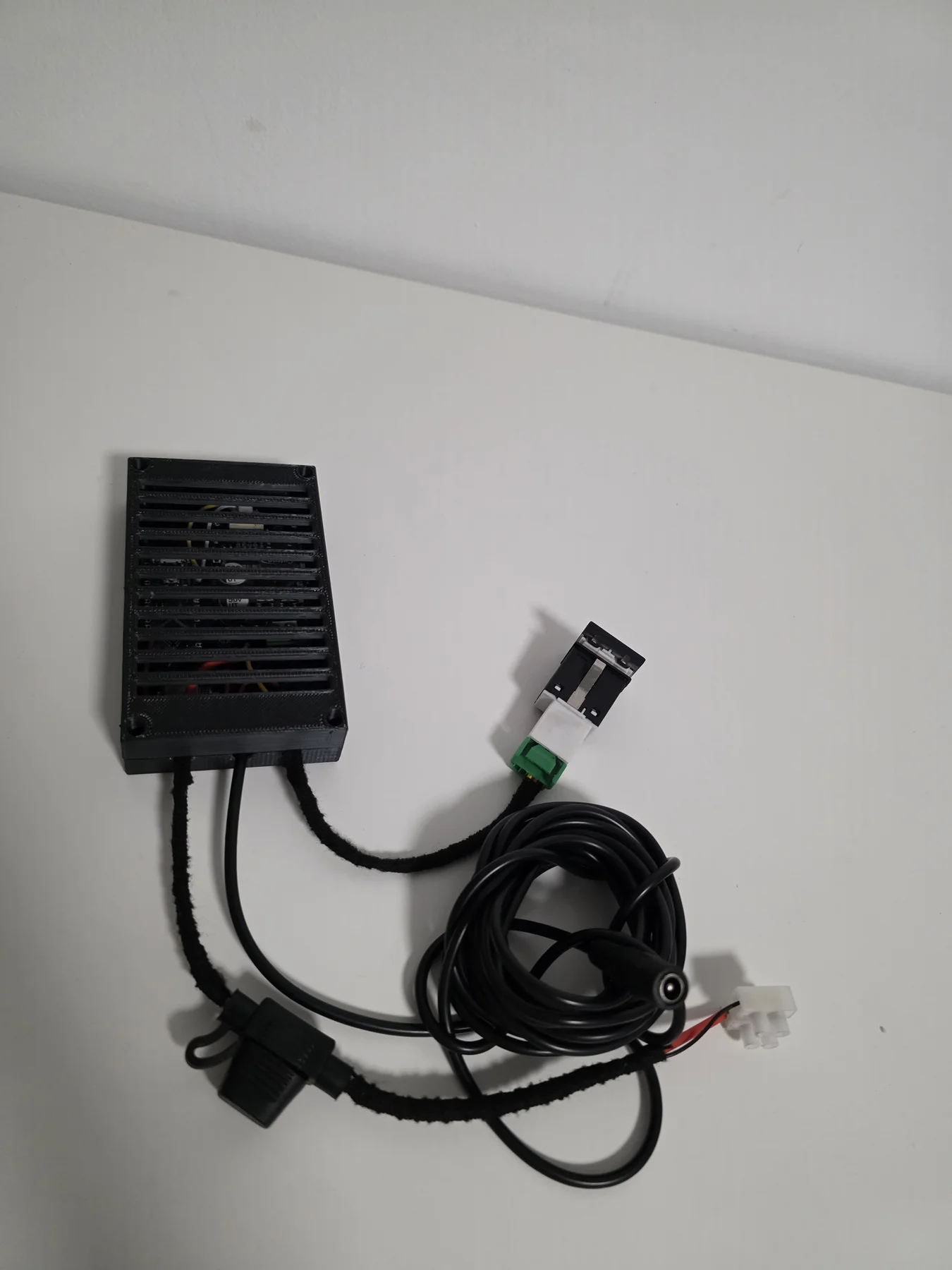
Finished exhaust controller unit
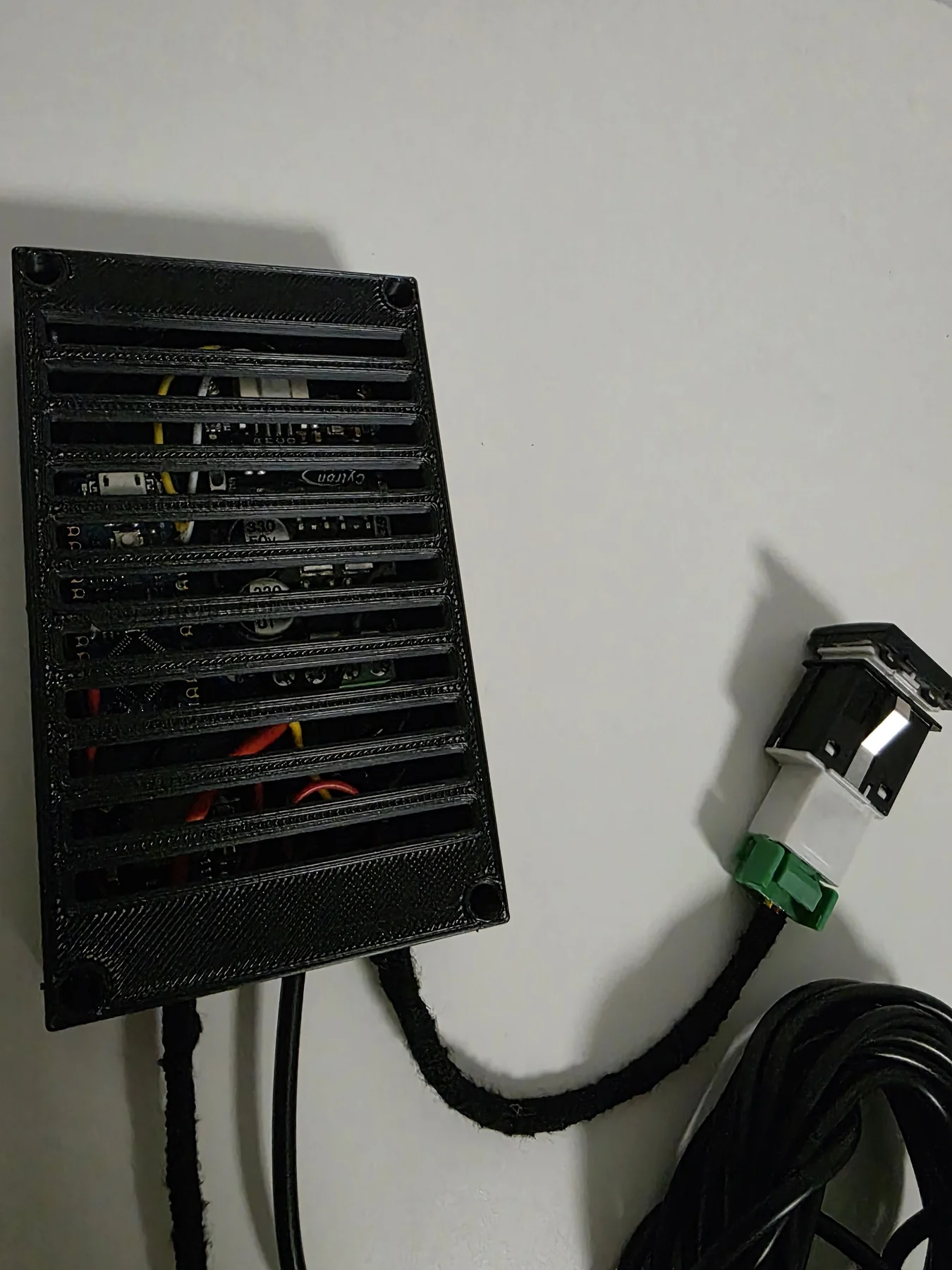
Finished unit — louvred enclosure & panel-mount switch
Finished unit
Enclosure open
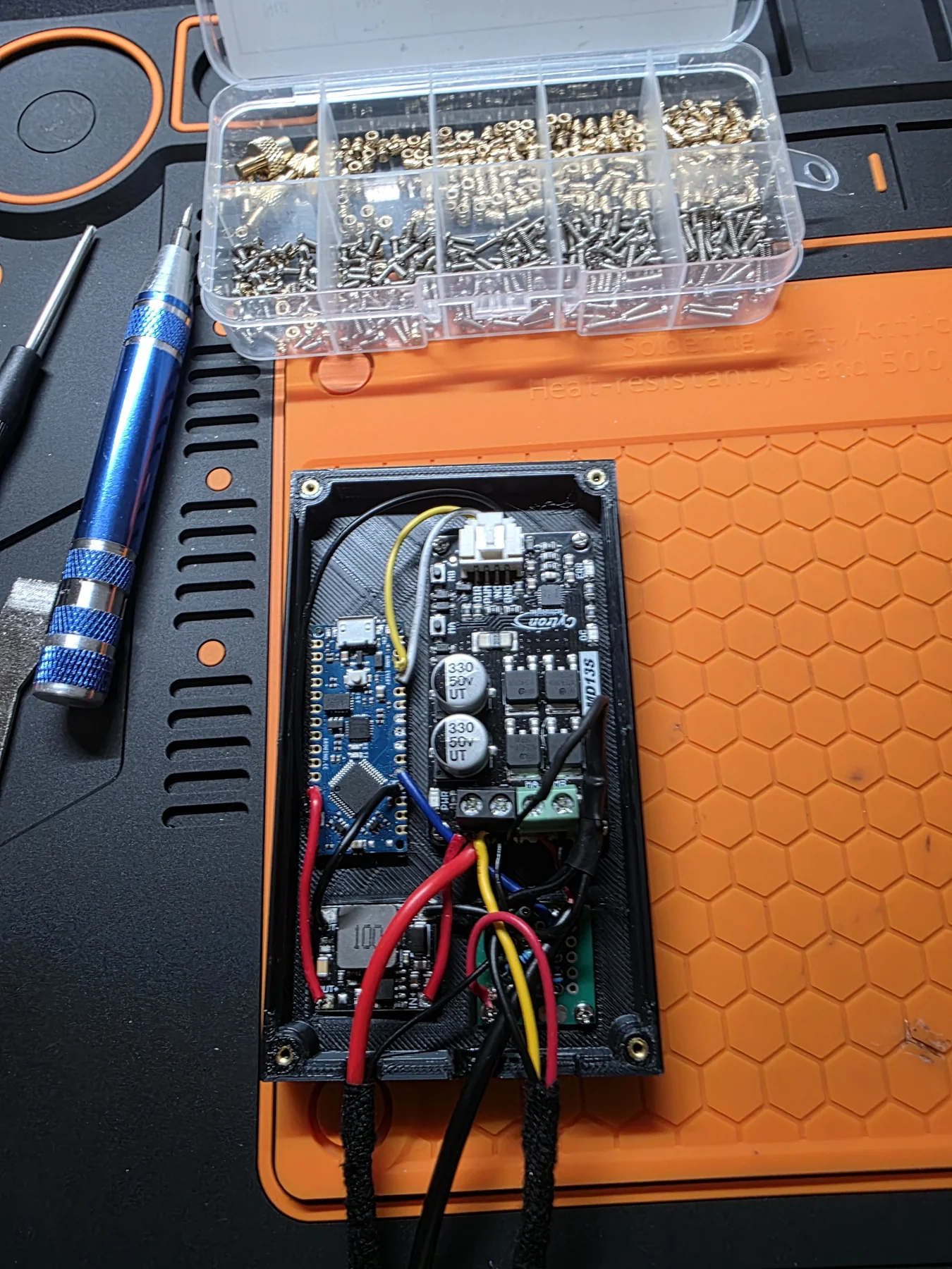
Electronics installed
Arduino Nano
Wired
Assembly
Wiring harness
Enclosure parts
Enclosure detail
Installed view
Key Components
Arduino Nano
MD13S Cytron
3A Buck Conv.
Push Button
Valve Actuator
Fuse Holder
Fusion 360
Build Progress
✓
Concept
✓
CAD Design
✓
3D Print
✓
Wiring
✓
Firmware
✓
Installed
What I Learned
  • A voltage divider is for reading signals, not powering circuits. Use an LDO for stable voltage under load.
  • Designing an enclosure around the components — not cramming them into a generic box — made the final unit look properly finished.
12 V
Car Power Input
13 A
Driver (overkill)
3 A
Buck Converter
#1
First Project Ever
Build walkthrough & electronics below ↓
MCU
Nano
Arduino ATmega328P
Motor Driver
MD13S
Cytron 13A DC driver
Car Power
12V
Stepped to 5V via buck
Project #
01
First hardware project ever
At a Glance
TypePersonal project (my first)
My roleSolo: wiring, enclosure CAD, install in the car
Timeline2025
Skills12 V automotive power · motor driver · enclosure design
ToolsArduino IDE · Fusion 360
StatusInstalled and working

Exhaust cutout valves are butterfly valves fitted in the exhaust pipe — open them and the exhaust bypasses the silencer, giving a much louder tone. Normally these are controlled by a simple toggle switch wired directly to a relay. I decided to put an Arduino in the middle of that, which in hindsight added complexity for no real benefit. But I learned a lot doing it.

The car runs 12V. I needed 5V for the Arduino Nano and a logic-level signal to drive the MD13S motor driver controlling the valve actuator. I used a 3A DC-DC buck converter to step the 12V down to 5V, which was the right call. I also used a voltage divider to get 3.3V for a reference signal — I later confirmed through university coursework that this is not the correct approach for powering a circuit; the output voltage drops under load. A proper LDO regulator is the right answer, and it does work in this project only because the 3.3V line carries very little current.

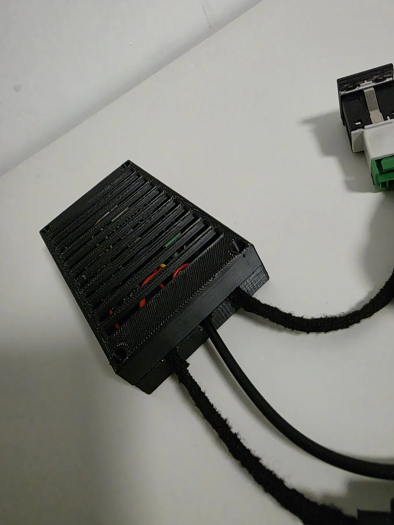
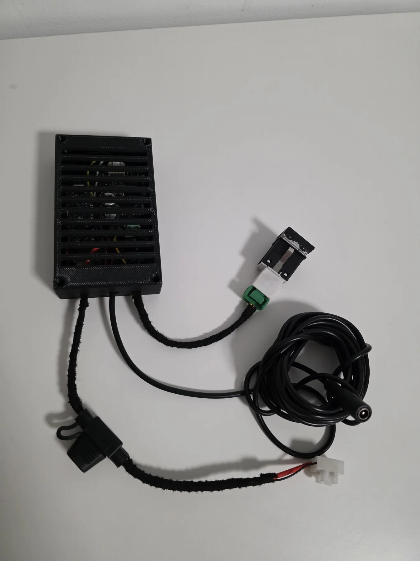
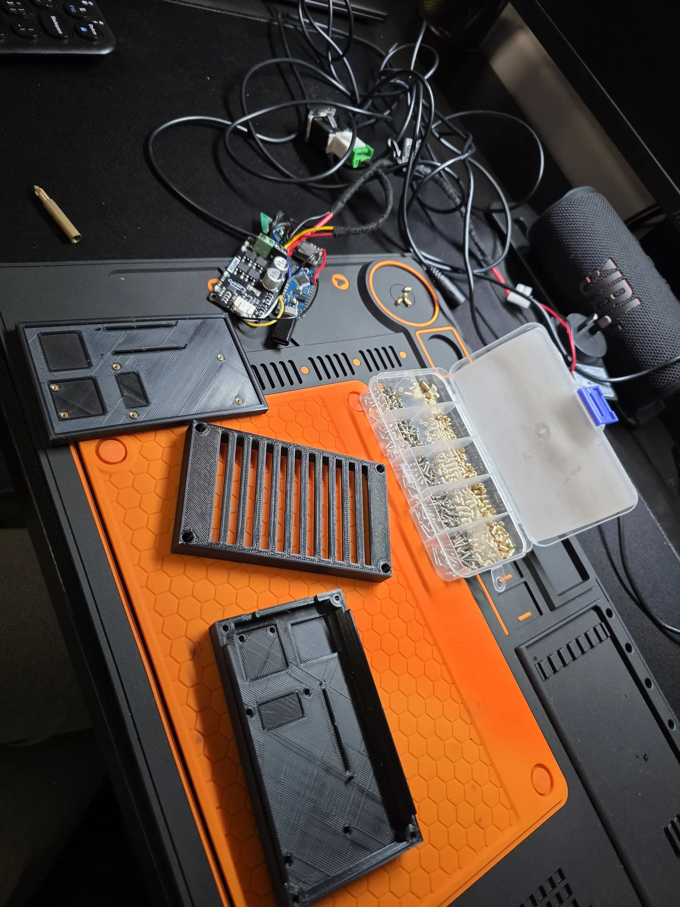
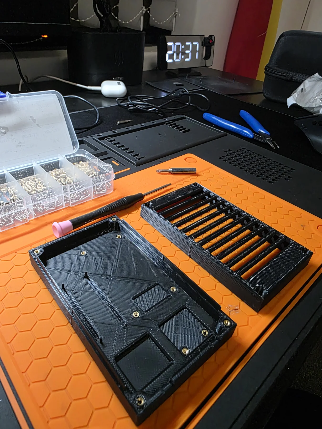
The enclosure was the part I put the most thought into. Designed entirely in Fusion 360, printed in black PLA — the box has internal posts so every PCB and module screws in at a fixed position. The top cover has ventilation louvres. The wiring exits through a grommet hole. For a first project, it looked properly finished.

Build
Step 01
Enclosure design in Fusion 360
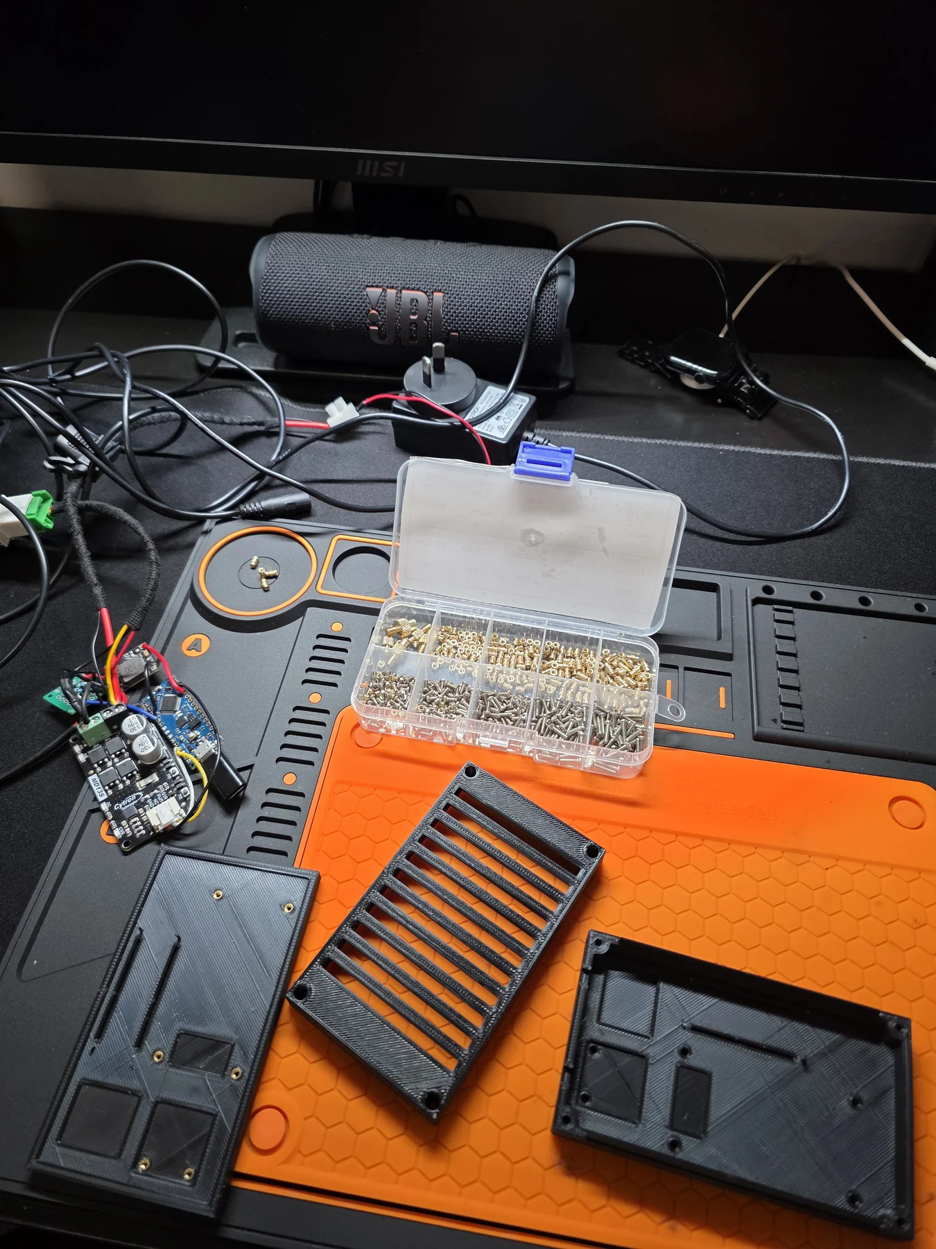
Modelled a rectangular enclosure with internal mounting posts at exactly the right positions for the Arduino Nano and the MD13S driver. The top cover has horizontal louvres for airflow and a flat mounting face. Designed so all components screw in — no hot glue, no cable ties.
3D-printed enclosure halves
Printed enclosure — base and cover halves
Step 02
Electronics — power circuit and driver
12V in from the car battery → 3A DC-DC buck converter → 5V for the Arduino Nano. The MD13S Cytron 13A motor driver is overkill for an exhaust valve actuator (which draws maybe 1–2A peak), but it was what was available and easy to wire. I also added a voltage divider for a 3.3V reference — as I later learned in university, this is not the correct approach for powering a circuit, but it functions in this project because the 3.3V line draws very little current.
Electronics installed in enclosure
Electronics mounted — MD13S, buck converter, Arduino
Step 03
Arduino Nano — firmware
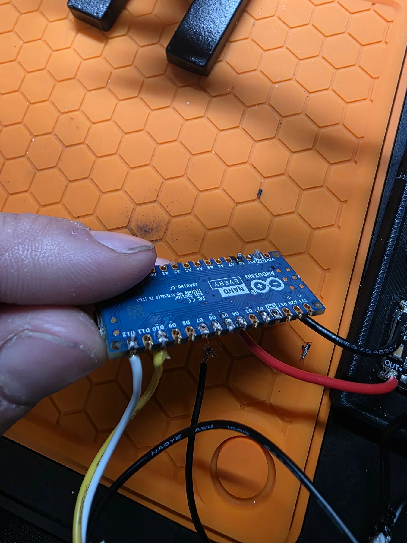
The Arduino Nano firmware is simple: read a debounced push button input, toggle a boolean state, drive the MD13S direction pins accordingly to open or close the valve. The car DRL red LED lights up when the cutout is open — wired through the same output to give a visual status indicator on the dash without needing a separate LED.
Arduino Nano
Arduino Nano with wiring
Step 04
Assembly and wiring harness
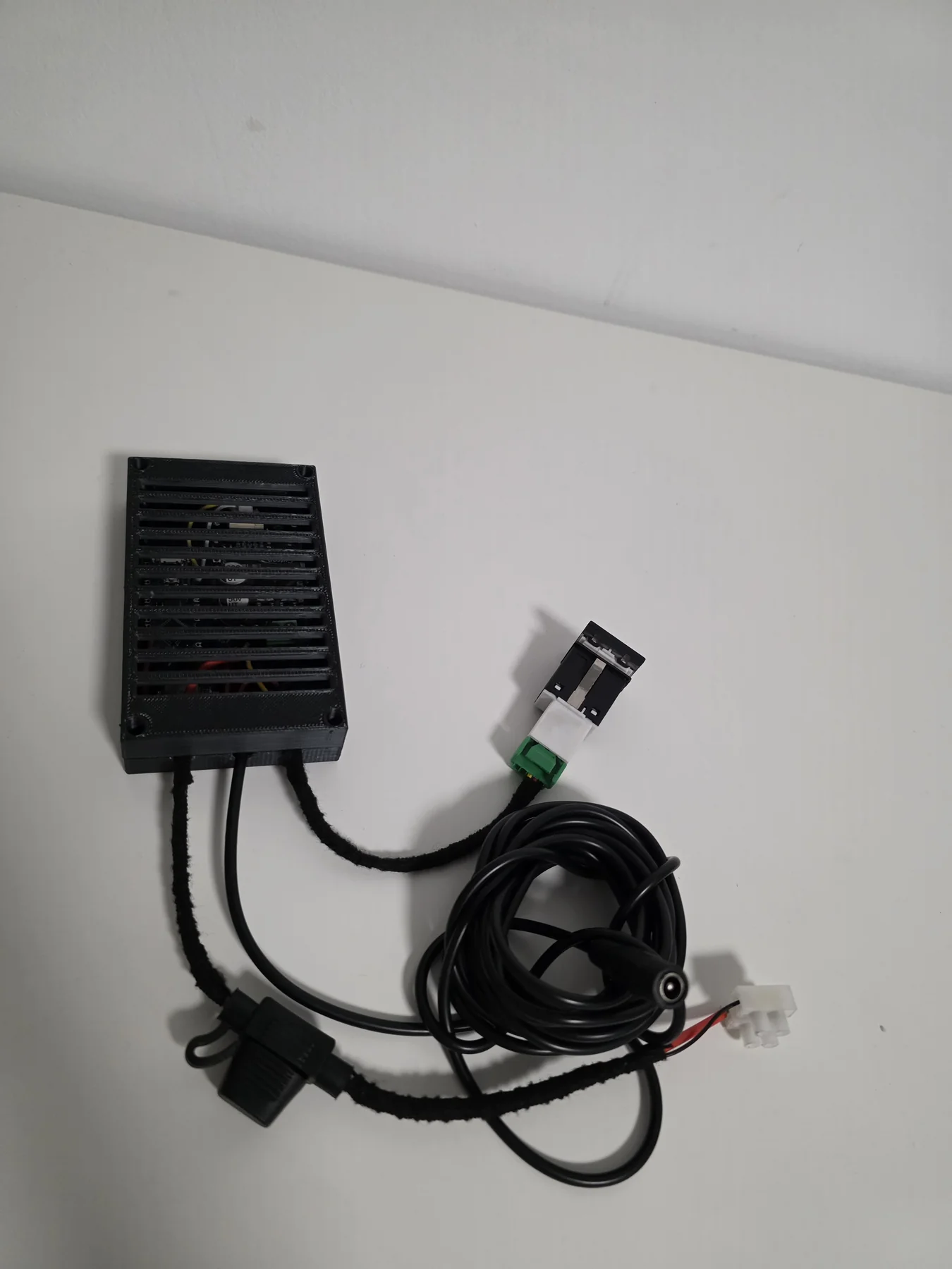
All boards screwed into the enclosure posts. Wiring exits through a single grommet hole, split into a sleeved harness — power in (12V from fuse box), motor output to valve, and switch/LED wires to dash. The finished unit bolts under the dash or into the boot with two screws through the enclosure flanges.
Finished unit with wiring harness
Finished controller — enclosure, switch, wiring harness

Electronics

Component List
MicrocontrollerArduino Nano (ATmega328P, 16 MHz, CH340)
Motor driverMD13S Cytron 13A (oversized)
Buck converter3A DC-DC step-down · 12V → 5V
3.3V referenceVoltage divider (wrong approach)
InputPush button with debounce in firmware
IndicatorCar red DRL LED — open/closed status
Power input12V car fuse box
FuseWaterproof inline fuse holder — main power line
EnclosureFusion 360, 3D-printed PLA
What I'd Do Differently
Motor driverL9110S or small relay — 1–2A is enough
3.3V supplyAMS1117-3.3 LDO, not a voltage divider
MCUATtiny85 — no need for full Arduino
WiringProper connector housing, not bare headers
Enclosure mountDIN rail clips instead of bolt holes
Voltage divider for 3.3V — the wrong call
A voltage divider uses two resistors to create a ratio of the input voltage. It works fine with no load — but as soon as you draw current, the output voltage drops because the resistor values change the division ratio under load. The correct approach for powering a circuit at 3.3V from 5V is an LDO regulator (like the AMS1117-3.3), which maintains a stable output regardless of load. I later confirmed this through university coursework — it's one of those things that works in a low-current situation and hides its own flaw until it doesn't.
MD13S 13A motor driver for a 1A actuator
The MD13S is a 13A capable driver meant for large motors. The exhaust valve actuator draws maybe 1–2A peak. Using a 13A driver here is like using a truck to deliver a letter — it works, but you're carrying around hardware that exists for a completely different application. A simple relay or an L9110S module would have been smaller, cheaper, and less confusing to wire.
The enclosure design was worth the effort
Spending time in Fusion 360 designing proper mounting posts for every component was the best decision of the project. Everything screwed in firmly, nothing shifted during installation, and the finished unit looked like something that belonged in a car. This approach — designing enclosures around components rather than cramming components into a generic box — carried over to every project after this one.

What I Learned

Lesson 01
Voltage regulators, not voltage dividers
A voltage divider is for reading a signal, not powering a circuit. If you need a stable lower voltage under load, use an LDO. This is the kind of thing that seems fine when you test it with a multimeter and no load attached — then fails the moment you connect something real.
Lesson 02
Match components to the actual requirement
An exhaust valve actuator does not need a 13A motor driver. Checking the actual motor current spec before choosing the driver would have saved money and board space. This lesson directly influenced every component selection after this project.
Lesson 03
A designed enclosure is worth the CAD time
The firmware took an afternoon. The enclosure design took two days. The firmware runs quietly in the background — the enclosure is what you see and handle every time you use the thing. Getting it right mattered more than it seemed at the time.

What came next

Project 02
Large RC Car — v1
First big self-designed project. Fusion 360 chassis, custom ESP-NOW remote — same over-engineering instincts, but on a bigger scale.
→
⌂ Portfolio Large RC Car →