Iterations
4
Specific → universal
Final width
370mm
Two 185mm halves
Mechanism
Slots
Slide + screw lock
Tool
Fusion
Fusion 360 + PETG
At a Glance
TypePersonal project
My roleSolo: design, printing, fitting
SkillsDesign iteration · parametric CAD · design for printing
ToolsFusion 360 · PLA prototypes · PETG final
ResultFour versions, ending in a universal design
The goal from the start was a clean plate mount — no visible screws from the front, nothing that looks aftermarket. Four versions later, the design is universal. But the first three needed to exist for the fourth to make sense.
The design point
The constraint wasn't in the problem — it was in the assumption
Three designs in, everything worked. The issue was I'd built my plate's exact dimensions into the sketch without realising it was a choice. Once I saw that, the fix was simple: make the width adjustable, not fixed. Same two printed halves, any plate size.
Design Stages
Stage
01
01
1
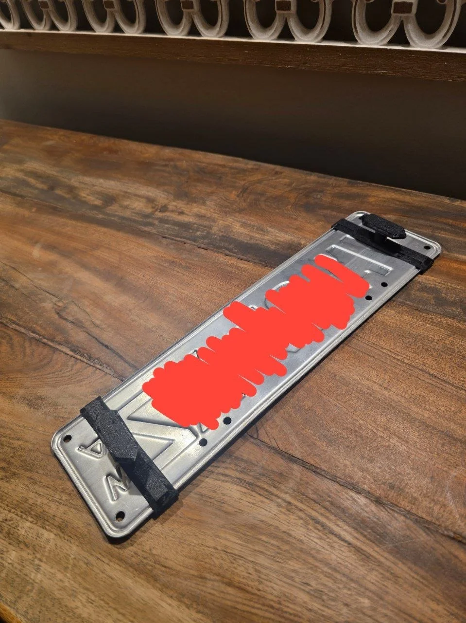
Rear plate holder — first design
Fusion 360 · Flat panel · PETG · Fixed to one plate size
Measured the plate, modelled a two-panel holder around those dimensions. Prototyped in PLA, final print in black PETG for outdoor durability.
Worked well — but every dimension was sized to my specific plate without me realising that was a choice.
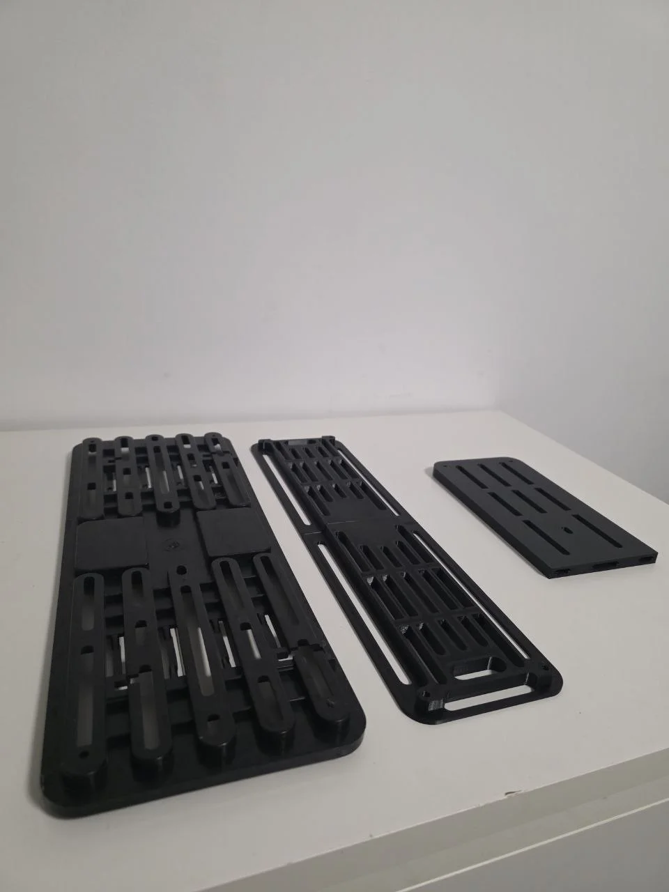
Left: original factory holder · Centre: Stage 1 final · Right: first prototype half
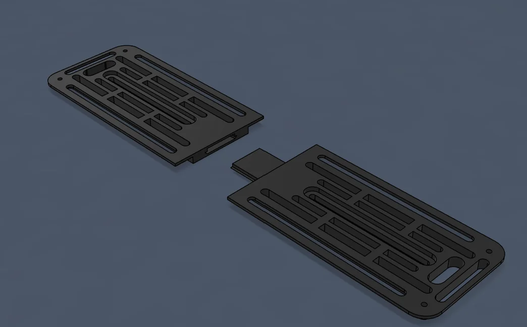
Stage 1 — two-panel design, disassembled
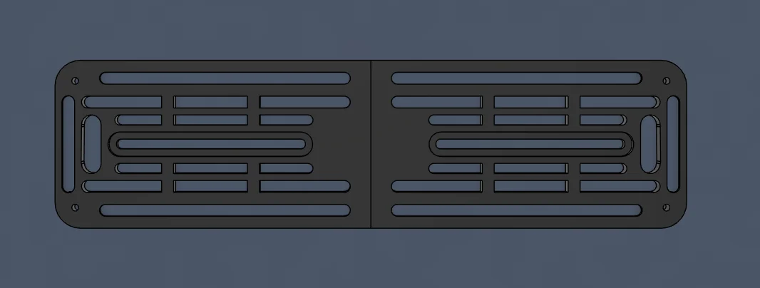
Stage 1 — top view showing panel profile
Stage
02
02
2
Front mesh bracket
Fusion 360 · Clips into Audi honeycomb grille · M3 screw lock · PETG
Different problem: mount to an Audi honeycomb grille with no holes drilled.
Two printed feet wedge behind the grille cells; an M3 screw through a threaded post clamps tight against the mesh from inside.
Had to be thin enough to clear the grille opening and stiff enough for road vibration — the post and T-nut base are a proper fastener pair, not a friction fit.
Still installed and in use.
Still installed and in use.
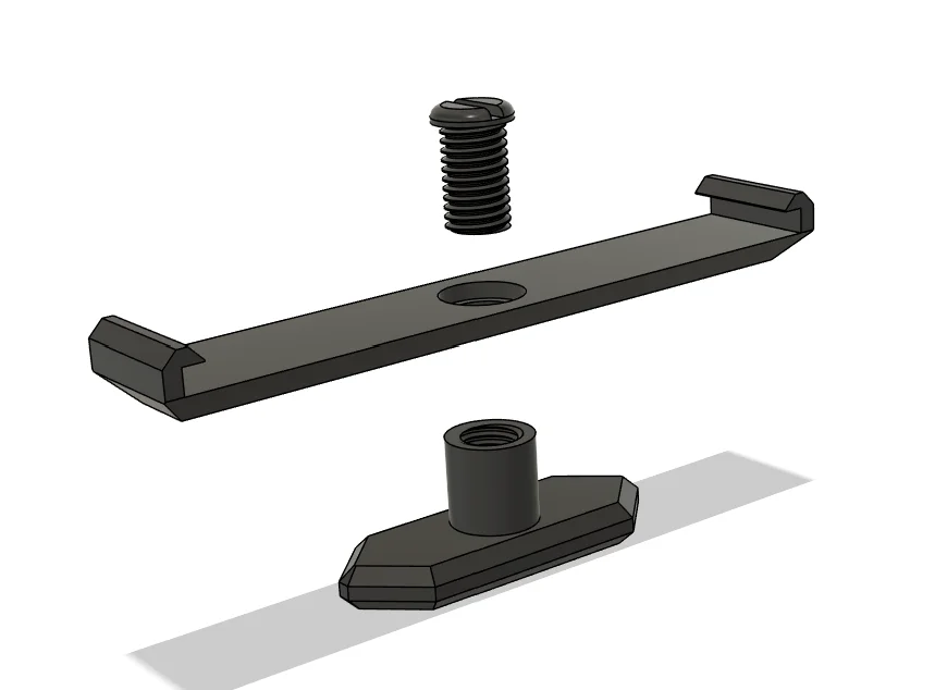
Exploded — bracket bar + threaded post + T-nut base
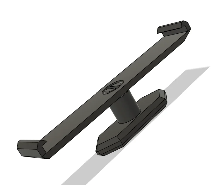
Assembled — screw pulls post through mesh cell
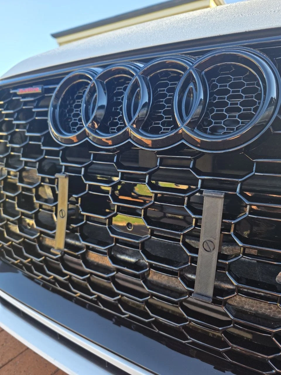
Installed — flush behind the Audi honeycomb grille, invisible from the front
Rear adjustable holder — sliding mechanism (Stage 4 design)
Stage
03
03
3
Rear holder — redesigned
Fusion 360 · Simplified profile · Less material, same function
After building the front bracket, it was obvious the Stage 1 rear design had more material than it needed.
Redesigned it using the same thinking: keep what carries load, remove the rest.
Slot cutouts replaced solid infill, corner bosses stayed. Simpler print, same clamping action.
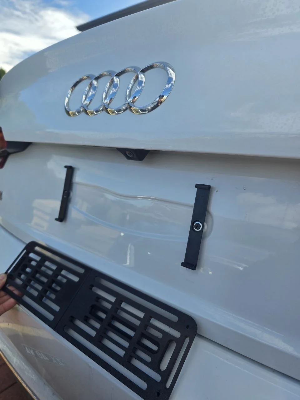
Installed on the car: Stage 3 (simplified clips). Being held: Stage 1 flat-panel original.
Stage
04
04
4
Adjustable universal holder
Fusion 360 · Sliding mechanism · M3 screw lock · Any plate width
One question looking at Stage 3: which dimensions actually need to be fixed? None of them.
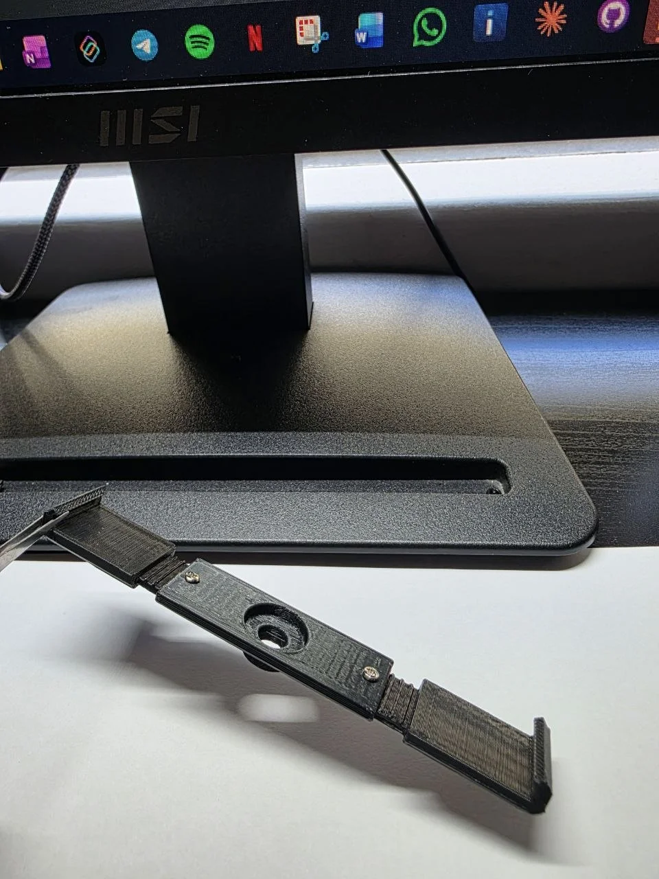
Split the design into two identical sliding halves. Each half has a row of elongated slots — the halves interlock, slide to whatever plate width you need, and lock with a central M3 screw through the overlapping slots. The same slot pattern that allows adjustment also reduces material. Two prints, one screw, works for any plate.
Split the design into two identical sliding halves. Each half has a row of elongated slots — the halves interlock, slide to whatever plate width you need, and lock with a central M3 screw through the overlapping slots. The same slot pattern that allows adjustment also reduces material. Two prints, one screw, works for any plate.
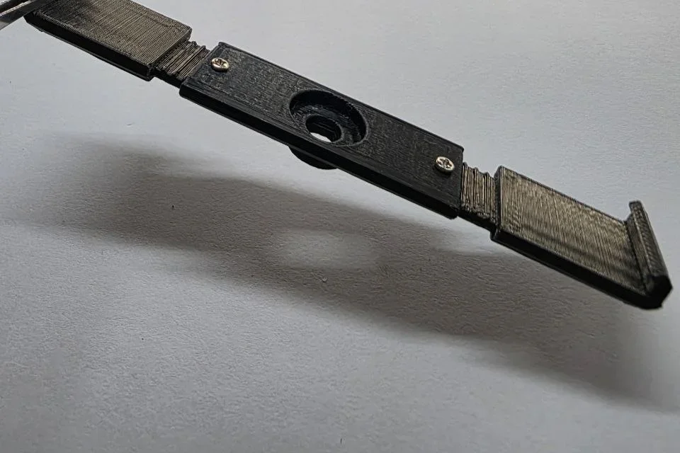
Printed — top view showing sliding mechanism and screw lock
Mechanism in action
Full range of motion
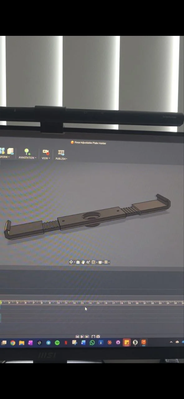
Fusion 360 — CAD model animation
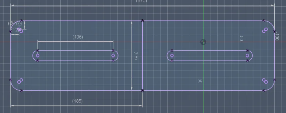
Dimensioned sketch — 370mm total, 100mm height, sliding range covers standard plate widths
Specs
| Stage 1 Rear — large |
Stage 2 Front mesh |
Stage 3 Rear — simplified |
Stage 4 Universal |
|
|---|---|---|---|---|
| Location | Rear | Front — grille | Rear | Rear |
| Material | PETG — black | PETG — black | PETG — black | PETG — black |
| Profile | Large · solid | 3-part assembly | Minimal · slotted | 2 × 185mm · 100mm H |
| Mount | Rear bumper clips | Clips into grille cells | Rear bumper clips | Rear bumper clips |
| Fastener | Screws | M3 + printed T-nut | Screws | M3 slot lock |
| Plate size | Fixed | Fixed | Fixed | Any width |
| Status | Superseded | Installed · in use | Superseded | Final design |